Archive for the ‘DC Microgrid’ Category

The DNO’s responsible for the technical operation in a medium and low voltage area, in which more than one Microgrids may exist. In addition, one or more MO’s are responsible for the Market Operation of this area. These two entities do not belong to the Microgrid, but they are the delegates of the grid. The DNO
refers to the operational functions of the system and the MO to the Market functions. It should be noted that, despite the autonomous operation of the Microgrid, it should ideally appear as a controlled, intelligent unit in coordination with the DNO.
The MGCC is the main responsible for the optimization of the Microgrid operation, or alternatively, it simply coordinates the local controllers, which assume the main responsibility for this optimization.
The LC’s control the Distributed Energy Resources (DER), production and storage units, and some of the local loads. Depending on themode of operation, they have certain level of intelligence, in order to take decisions locally. Of course, in any type of operation there are certain decisions that can be taken only locally.
Source:
Aris L. Dimeas, Nikos D. Natziargyriou «Operation of Multiagent System for Microgrid Control» IEEE Transactions on Power Systems, Vol. 20, No. 3, August 2005.
Dr. Jorge Luis Mírez Tarrillo
Group of Mathematical Modeling and Numerical Simulation (GMMNS).
Universidad Nacional de Ingeniería. Lima, Perú.
E-mail: jmirez@uni.edu.pe
Website Personal: https://jorgemirez2002.wixsite.com/jorgemirez
Facebook http://www.facebook.com/jorgemirezperu
Linkedin https://www.linkedin.com/in/jorge-luis-mirez-tarrillo-94918423/
Scopus ID: https://www.scopus.com/authid/detail.uri?authorId=56488109800
Google Scholar: https://scholar.google.com/citations?user=_dSpp4YAAAAJ
MATLAB Group Admin in Facebook: https://www.facebook.com/groups/Matlab.Simulink.for.All
WhatsApp Channel/Canal: https://whatsapp.com/channel/0029VbCvpZsAYlUSz2esek2y

Sun –> energy provided from photovoltaic energy plant.
Wind –> similar from wind turbine(s)
Batt –> similar from battery bank
ene –> similar injected from electrical network external or utility electric network
In other image in red is the total suministed for this sources and red line is the demand. Other images is cost, evoluction of energy supply from each source and more details. It is made for me (Jorge Mírez) in Matlabb/Simulink and I utilized concept of linear programming. Image is from my destokp laptop.
Dr. Jorge Luis Mírez Tarrillo
Group of Mathematical Modeling and Numerical Simulation (GMMNS).
Universidad Nacional de Ingeniería. Lima, Perú.
E-mail: jmirez@uni.edu.pe
Website Personal: https://jorgemirez2002.wixsite.com/jorgemirez
Facebook http://www.facebook.com/jorgemirezperu
Linkedin https://www.linkedin.com/in/jorge-luis-mirez-tarrillo-94918423/
Scopus ID: https://www.scopus.com/authid/detail.uri?authorId=56488109800
Google Scholar: https://scholar.google.com/citations?user=_dSpp4YAAAAJ
MATLAB Group Admin in Facebook: https://www.facebook.com/groups/Matlab.Simulink.for.All
WhatsApp Channel/Canal: https://whatsapp.com/channel/0029VbCvpZsAYlUSz2esek2y

The proposed DIEMS (distributed intelligent energy management system) allow instantaneous optimization of alternative and renewable power sources. The use of storage requires an optimization scheme that considers the time-integral part of the load flow. So, the energy management has to perform energy scheduling a single day or multiple days ahead. An intelligent energy management system in thus required which enables short-term energy allocation scheduling at minimun costs based on power generation and load demand. The function of the DIEMS is to generate set points for all the sources and storages in such a way that economically optimized power dispatch will be maintained to fulfill certain load demand. Generation forescast as well as some fast online algorithms are used to define the energy availability and, finally, to define the optimized power dispatch signals to the loads, as well as to the grid using UPLC (universal active power line conditioner). This energy management system, consists of prediction modulo, optimization module, and online control module, is shown in Figure.
Source:
Sudipta Chakraborty, Manoja D. Weiss and M. Godoy Simöes «Distributed Intelligent Energy Management System for a Single-Phase High-Frequency AC Microgrid» IEEE Transactions on Industrial Electronics. Vol. 54, No. 1, February 2007.
Dr. Jorge Luis Mírez Tarrillo
Group of Mathematical Modeling and Numerical Simulation (GMMNS).
Universidad Nacional de Ingeniería. Lima, Perú.
E-mail: jmirez@uni.edu.pe
Website Personal: https://jorgemirez2002.wixsite.com/jorgemirez
Facebook http://www.facebook.com/jorgemirezperu
Linkedin https://www.linkedin.com/in/jorge-luis-mirez-tarrillo-94918423/
Scopus ID: https://www.scopus.com/authid/detail.uri?authorId=56488109800
Google Scholar: https://scholar.google.com/citations?user=_dSpp4YAAAAJ
MATLAB Group Admin in Facebook: https://www.facebook.com/groups/Matlab.Simulink.for.All
WhatsApp Channel/Canal: https://whatsapp.com/channel/0029VbCvpZsAYlUSz2esek2y

There is a significative difference storage system and electric power system interconnection unit. The microgrid usually has as high power from grid point of view that it is connected to medium voltage fine, typically 15 kV in Poland. Although the power system interconnection unit has almost the structure as storage system, its primary voltage is in range of kilovolts and is sinusoidal. So, it requires different power electronic converter. It is assumed in Poland that all devices connected to 15 kV lines have to be joined using 50 Hz transformer. Hence, the grid interconnection unit can have a structure shown in Figure.
Source:
Piotr Biczel. “Power Electronic Converters in DC Microgrid”. IEEE 5th International Conference – Workshop, Compatibility in Power Electronics, CPE 2007. Poland.
Dr. Jorge Luis Mírez Tarrillo
Group of Mathematical Modeling and Numerical Simulation (GMMNS).
Universidad Nacional de Ingeniería. Lima, Perú.
E-mail: jmirez@uni.edu.pe
Website Personal: https://jorgemirez2002.wixsite.com/jorgemirez
Facebook http://www.facebook.com/jorgemirezperu
Linkedin https://www.linkedin.com/in/jorge-luis-mirez-tarrillo-94918423/
Scopus ID: https://www.scopus.com/authid/detail.uri?authorId=56488109800
Google Scholar: https://scholar.google.com/citations?user=_dSpp4YAAAAJ
MATLAB Group Admin in Facebook: https://www.facebook.com/groups/Matlab.Simulink.for.All
WhatsApp Channel/Canal: https://whatsapp.com/channel/0029VbCvpZsAYlUSz2esek2y

El block diagram structure of a microgrid is shown in Figure. The main task of the power plant’s power electronic converter is to fit primary energy converter’s output voltage to the microgrid power line voltage, and source operating point control as well as low and high level microgrid’s control. The converter’s structure depends on a type of primary energy converter. A common feature of the converters concerns their output current. It should be permanent and low ripple.
Source:
Piotr Biczel. “Power Electronic Converters in DC Microgrid”. IEEE 5th International Conference – Workshop, Compatibility in Power Electronics, CPE 2007. Poland.
Dr. Jorge Luis Mírez Tarrillo
Group of Mathematical Modeling and Numerical Simulation (GMMNS).
Universidad Nacional de Ingeniería. Lima, Perú.
E-mail: jmirez@uni.edu.pe
Website Personal: https://jorgemirez2002.wixsite.com/jorgemirez
Facebook http://www.facebook.com/jorgemirezperu
Linkedin https://www.linkedin.com/in/jorge-luis-mirez-tarrillo-94918423/
Scopus ID: https://www.scopus.com/authid/detail.uri?authorId=56488109800
Google Scholar: https://scholar.google.com/citations?user=_dSpp4YAAAAJ
MATLAB Group Admin in Facebook: https://www.facebook.com/groups/Matlab.Simulink.for.All
WhatsApp Channel/Canal: https://whatsapp.com/channel/0029VbCvpZsAYlUSz2esek2y

This is my simulation made on Matlab/Simulink about difference time of conextion in bank condensers. The reactive power change in the time and it is aleatory. In this context, the mathematical models have that made the emulation of this performance.
Dr. Jorge Luis Mírez Tarrillo
Group of Mathematical Modeling and Numerical Simulation (GMMNS).
Universidad Nacional de Ingeniería. Lima, Perú.
E-mail: jmirez@uni.edu.pe
Website Personal: https://jorgemirez2002.wixsite.com/jorgemirez
Facebook http://www.facebook.com/jorgemirezperu
Linkedin https://www.linkedin.com/in/jorge-luis-mirez-tarrillo-94918423/
Scopus ID: https://www.scopus.com/authid/detail.uri?authorId=56488109800
Google Scholar: https://scholar.google.com/citations?user=_dSpp4YAAAAJ
MATLAB Group Admin in Facebook: https://www.facebook.com/groups/Matlab.Simulink.for.All
WhatsApp Channel/Canal: https://whatsapp.com/channel/0029VbCvpZsAYlUSz2esek2y

Any Condenser Bank have many condensers of equal or different capacity. Its is connected in function to the need of reactive power in the distributed network or microsource connected. The change time in the real world is aleatory and stochastic. This figure is a emulation by this problem. Maximum time change of 5 minutes (8.333 in this vertical scale). Horizontal scale is the progressive number times of realization change
Dr. Jorge Luis Mírez Tarrillo
Group of Mathematical Modeling and Numerical Simulation (GMMNS).
Universidad Nacional de Ingeniería. Lima, Perú.
E-mail: jmirez@uni.edu.pe
Website Personal: https://jorgemirez2002.wixsite.com/jorgemirez
Facebook http://www.facebook.com/jorgemirezperu
Linkedin https://www.linkedin.com/in/jorge-luis-mirez-tarrillo-94918423/
Scopus ID: https://www.scopus.com/authid/detail.uri?authorId=56488109800
Google Scholar: https://scholar.google.com/citations?user=_dSpp4YAAAAJ
MATLAB Group Admin in Facebook: https://www.facebook.com/groups/Matlab.Simulink.for.All
WhatsApp Channel/Canal: https://whatsapp.com/channel/0029VbCvpZsAYlUSz2esek2y
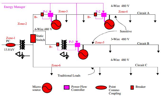
The CERTS Microgrid program has developed control methods to allow the installation of distributed generators (DGs) in commercial and industrial electric power systems in a “plug and play” manner. These control methods allow the generators to be electrically distributed, rather than be installed on the same electrical bus, and do not require intergenerator communications in order to maintain appropriate voltage and frequency at each generator. Note in figure that there is a communication link with the DGs that is labeled “Energy Manager”. This is a conventional energy manager that is used for power dispatch purposes, not for frequency or voltage control. This energy manager can use relatively slow communications links, such as telephone or internet, since it has no bearing on system stability.
Source:
John Stevens «CERTS Microgrid System Test». IEEExplore
Dr. Jorge Luis Mírez Tarrillo
Group of Mathematical Modeling and Numerical Simulation (GMMNS).
Universidad Nacional de Ingeniería. Lima, Perú.
E-mail: jmirez@uni.edu.pe
Website Personal: https://jorgemirez2002.wixsite.com/jorgemirez
Facebook http://www.facebook.com/jorgemirezperu
Linkedin https://www.linkedin.com/in/jorge-luis-mirez-tarrillo-94918423/
Scopus ID: https://www.scopus.com/authid/detail.uri?authorId=56488109800
Google Scholar: https://scholar.google.com/citations?user=_dSpp4YAAAAJ
MATLAB Group Admin in Facebook: https://www.facebook.com/groups/Matlab.Simulink.for.All
WhatsApp Channel/Canal: https://whatsapp.com/channel/0029VbCvpZsAYlUSz2esek2y

Many examples there is in this blog about DC microgrids (see last post or search in blog). This blog is for share information of actual tendence in electricity. It is part of my research as doctoral student in physics in National University of Engineering in Lima, Perú; and actually I am writing in english. For last post, the blog have a traductor box option. Near to 1000 post about diferents topic in renewable energy focused in microgrid, smartgrid and its modelling ans simulation witn Matlab/Simulink. I know this software and its very good, practical for science and engineering. In May or June is possible I will expose mi thesys doctoral, previus days or weeks I posted the exact time for all people see in live or via internet. This figure is other DC microgrid scheme with different technologies interconnected at a some bus DC for transfered electric power. Jorge Mírez (please visit and link my fanpage http://www.facebook.com/jorgemirezperu )
Source of Figure:
N. R. Rahmanov, N. M. Tabatabaei, K. Dursun, O. Z. Kerimov. “Combined AC-DC Microgrids: Case Study – Network Development and Simulation” International Journal on Technical and Physical Problems of Engineering. September 2012, Issue 12, Volume 4, Number 3, Pages 157 – 161.
Dr. Jorge Luis Mírez Tarrillo
Group of Mathematical Modeling and Numerical Simulation (GMMNS).
Universidad Nacional de Ingeniería. Lima, Perú.
E-mail: jmirez@uni.edu.pe
Website Personal: https://jorgemirez2002.wixsite.com/jorgemirez
Facebook http://www.facebook.com/jorgemirezperu
Linkedin https://www.linkedin.com/in/jorge-luis-mirez-tarrillo-94918423/
Scopus ID: https://www.scopus.com/authid/detail.uri?authorId=56488109800
Google Scholar: https://scholar.google.com/citations?user=_dSpp4YAAAAJ
MATLAB Group Admin in Facebook: https://www.facebook.com/groups/Matlab.Simulink.for.All
WhatsApp Channel/Canal: https://whatsapp.com/channel/0029VbCvpZsAYlUSz2esek2y

In the office there are many electronic equipment, it for the general, to use DC voltage. There is certain paradigme about the data center made more for market that for technical reasons… ups, many companies it not like. Ok, the figure shown the special configuration (a example) of electrical supply to equipment office. Very good, it is a representative used of potential DC microgrids.
Source of Figure:
N. R. Rahmanov, N. M. Tabatabaei, K. Dursun, O. Z. Kerimov. «Combined AC-DC Microgrids: Case Study – Network Development and Simulation» International Journal on Technical and Physical Problems of Engineering. September 2012, Issue 12, Volume 4, Number 3, Pages 157 – 161.
Dr. Jorge Luis Mírez Tarrillo
Group of Mathematical Modeling and Numerical Simulation (GMMNS).
Universidad Nacional de Ingeniería. Lima, Perú.
E-mail: jmirez@uni.edu.pe
Website Personal: https://jorgemirez2002.wixsite.com/jorgemirez
Facebook http://www.facebook.com/jorgemirezperu
Linkedin https://www.linkedin.com/in/jorge-luis-mirez-tarrillo-94918423/
Scopus ID: https://www.scopus.com/authid/detail.uri?authorId=56488109800
Google Scholar: https://scholar.google.com/citations?user=_dSpp4YAAAAJ
MATLAB Group Admin in Facebook: https://www.facebook.com/groups/Matlab.Simulink.for.All
WhatsApp Channel/Canal: https://whatsapp.com/channel/0029VbCvpZsAYlUSz2esek2y

This a typical scheme of a microgrid AC/DC. It maybe contain many technologies as micro-source, storage, loads and monitoring and control. Un Microgrid Bus linked the different components.
Source:
N. R. Rahmanov, N. M. Tabatabaei, K. Dursun, O. Z. Kerimov. «Combined AC-DC Microgrids: Case Study – Network Development and Simulation» International Journal on Technical and Physical Problems of Engineering. September 2012, Issue 12, Volume 4, Number 3, Pages 157 – 161.
Dr. Jorge Luis Mírez Tarrillo
Group of Mathematical Modeling and Numerical Simulation (GMMNS).
Universidad Nacional de Ingeniería. Lima, Perú.
E-mail: jmirez@uni.edu.pe
Website Personal: https://jorgemirez2002.wixsite.com/jorgemirez
Facebook http://www.facebook.com/jorgemirezperu
Linkedin https://www.linkedin.com/in/jorge-luis-mirez-tarrillo-94918423/
Scopus ID: https://www.scopus.com/authid/detail.uri?authorId=56488109800
Google Scholar: https://scholar.google.com/citations?user=_dSpp4YAAAAJ
MATLAB Group Admin in Facebook: https://www.facebook.com/groups/Matlab.Simulink.for.All
WhatsApp Channel/Canal: https://whatsapp.com/channel/0029VbCvpZsAYlUSz2esek2y

DC grid of a Microgrid DC may be unipolar with ground as return path or bipolar with positive and negative terminal. The figure (a) and (b) depicts unipolar and bipolar grid respectively. If load connected to DC bus is DC such as TV, computers, fluorescent lamps; DC bus requires less power conversion stages. Since power conversion stages are less, losses in conversion also gets reduced.
Source:
Ganesh Patil, M. F. A. R. Satarkar, Gorakshanath Abande «New Scheme for Protection of DC Micro grid» International Journal of Innovative Reseach in Science, Engineering and Technology. Volume 3, Special Issue 3, March 2014.
Dr. Jorge Luis Mírez Tarrillo
Group of Mathematical Modeling and Numerical Simulation (GMMNS).
Universidad Nacional de Ingeniería. Lima, Perú.
E-mail: jmirez@uni.edu.pe
Website Personal: https://jorgemirez2002.wixsite.com/jorgemirez
Facebook http://www.facebook.com/jorgemirezperu
Linkedin https://www.linkedin.com/in/jorge-luis-mirez-tarrillo-94918423/
Scopus ID: https://www.scopus.com/authid/detail.uri?authorId=56488109800
Google Scholar: https://scholar.google.com/citations?user=_dSpp4YAAAAJ
MATLAB Group Admin in Facebook: https://www.facebook.com/groups/Matlab.Simulink.for.All
WhatsApp Channel/Canal: https://whatsapp.com/channel/0029VbCvpZsAYlUSz2esek2y

The figure illustrates the concept of the power management method in the islanded mode. When a DC micro-grid must be separated from the ac grid and switch to the islanded mode, the grid-tied converter released control of the DC grid voltage and one of the converters in the micro-grid must take over that control. Since each converter of DGs is used for optimal control of each source, only the converters of the energy storage elements are free to regulate the DC grid voltage. During the islanded mode, the battery plays a main role in regulating the DC grid voltage and the super-capacitor plays a secondary role in responding to the sudden power requirement as an auxiliary converter.
Source:
Ji-Heon Lee, Hyun-Jun Kim, Byung-Moon Han, Yu-Seok Jeong, Hyo-Sik Yang and Han-Ju Cha “DC Micro-Grid Operational Analysis with a Detailed Simulation Model for Distributed Generation” Journal of Power Electronics, Vol. 11, No. 3, May 2011
Dr. Jorge Luis Mírez Tarrillo
Group of Mathematical Modeling and Numerical Simulation (GMMNS).
Universidad Nacional de Ingeniería. Lima, Perú.
E-mail: jmirez@uni.edu.pe
Website Personal: https://jorgemirez2002.wixsite.com/jorgemirez
Facebook http://www.facebook.com/jorgemirezperu
Linkedin https://www.linkedin.com/in/jorge-luis-mirez-tarrillo-94918423/
Scopus ID: https://www.scopus.com/authid/detail.uri?authorId=56488109800
Google Scholar: https://scholar.google.com/citations?user=_dSpp4YAAAAJ
MATLAB Group Admin in Facebook: https://www.facebook.com/groups/Matlab.Simulink.for.All
WhatsApp Channel/Canal: https://whatsapp.com/channel/0029VbCvpZsAYlUSz2esek2y
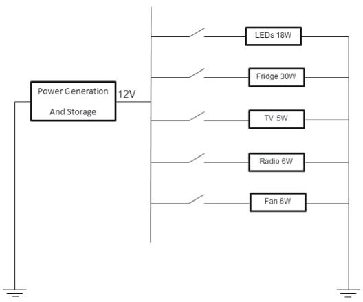
The figure shows the simplified distribution system of the DC microgrid system. The wire sizing has to comply with the South Africa National Standard (SANS) on the wiring of premises 6 mm2 for the generation and storage side, and 2.5 mm2 for the distribution side will allow an acceptable tolerance of voltage drop for this low voltage system, refer to SANS 10142
Source:
Gilbert M Bokanga, Atanda Raji, Mohammed TE Kahn. “Design of a low voltage DC microgrid system for rural electrification in South Africa”. Journal of Energy in Southern Africa • Vol 25 No 2 • May 2014.
Dr. Jorge Luis Mírez Tarrillo
Group of Mathematical Modeling and Numerical Simulation (GMMNS).
Universidad Nacional de Ingeniería. Lima, Perú.
E-mail: jmirez@uni.edu.pe
Website Personal: https://jorgemirez2002.wixsite.com/jorgemirez
Facebook http://www.facebook.com/jorgemirezperu
Linkedin https://www.linkedin.com/in/jorge-luis-mirez-tarrillo-94918423/
Scopus ID: https://www.scopus.com/authid/detail.uri?authorId=56488109800
Google Scholar: https://scholar.google.com/citations?user=_dSpp4YAAAAJ
MATLAB Group Admin in Facebook: https://www.facebook.com/groups/Matlab.Simulink.for.All
WhatsApp Channel/Canal: https://whatsapp.com/channel/0029VbCvpZsAYlUSz2esek2y

Hybrid renewable energy systems have been accepted as possible means of electrifying rural outlying areas where it is too expensive to extend the grid to supply them. As stipulated in the introduction, the system is intended to power households, and it must be cost effective; therefore, only solar energy system is retained. Figure 1 shows the overview of the low voltage DC microgrid system
Source:
Gilbert M Bokanga, Atanda Raji, Mohammed TE Kahn. «Design of a low voltage DC microgrid system for rural electrification in South Africa». Journal of Energy in Southern Africa • Vol 25 No 2 • May 2014.
Dr. Jorge Luis Mírez Tarrillo
Group of Mathematical Modeling and Numerical Simulation (GMMNS).
Universidad Nacional de Ingeniería. Lima, Perú.
E-mail: jmirez@uni.edu.pe
Website Personal: https://jorgemirez2002.wixsite.com/jorgemirez
Facebook http://www.facebook.com/jorgemirezperu
Linkedin https://www.linkedin.com/in/jorge-luis-mirez-tarrillo-94918423/
Scopus ID: https://www.scopus.com/authid/detail.uri?authorId=56488109800
Google Scholar: https://scholar.google.com/citations?user=_dSpp4YAAAAJ
MATLAB Group Admin in Facebook: https://www.facebook.com/groups/Matlab.Simulink.for.All
WhatsApp Channel/Canal: https://whatsapp.com/channel/0029VbCvpZsAYlUSz2esek2y

This is a part of my results about interconnected of two microgrids. It have flow power in function a its capacities, but probably a deficit and/or surplus in supply or demand in both microgrids is present. Negative is deficit in microgrid to import from other source different to other microgrid. Positivo is surplus in microgrid by export to other demand different at other microgrid. The figure is a simple example for to show that it is possible using mathematical modelling and simulations on Matlab of MathWork Inc.
Dr. Jorge Luis Mírez Tarrillo
Group of Mathematical Modeling and Numerical Simulation (GMMNS).
Universidad Nacional de Ingeniería. Lima, Perú.
E-mail: jmirez@uni.edu.pe
Website Personal: https://jorgemirez2002.wixsite.com/jorgemirez
Facebook http://www.facebook.com/jorgemirezperu
Linkedin https://www.linkedin.com/in/jorge-luis-mirez-tarrillo-94918423/
Scopus ID: https://www.scopus.com/authid/detail.uri?authorId=56488109800
Google Scholar: https://scholar.google.com/citations?user=_dSpp4YAAAAJ
MATLAB Group Admin in Facebook: https://www.facebook.com/groups/Matlab.Simulink.for.All
WhatsApp Channel/Canal: https://whatsapp.com/channel/0029VbCvpZsAYlUSz2esek2y

This is part of my results in Matlab about power flow between two microgrids interconected. In different color shown the direction of power flow (from Microgrid 1 to Microgrid 2, and from Microgrid 2 to Microgrid 1). The figure is a simple example for to show that it is possible using mathematical modelling and simulations on Matlab of MathWork Inc.
Dr. Jorge Luis Mírez Tarrillo
Group of Mathematical Modeling and Numerical Simulation (GMMNS).
Universidad Nacional de Ingeniería. Lima, Perú.
E-mail: jmirez@uni.edu.pe
Website Personal: https://jorgemirez2002.wixsite.com/jorgemirez
Facebook http://www.facebook.com/jorgemirezperu
Linkedin https://www.linkedin.com/in/jorge-luis-mirez-tarrillo-94918423/
Scopus ID: https://www.scopus.com/authid/detail.uri?authorId=56488109800
Google Scholar: https://scholar.google.com/citations?user=_dSpp4YAAAAJ
MATLAB Group Admin in Facebook: https://www.facebook.com/groups/Matlab.Simulink.for.All
WhatsApp Channel/Canal: https://whatsapp.com/channel/0029VbCvpZsAYlUSz2esek2y

The dc microgrid considered is schematically shown in Fig. As for a typical dc microgrid, it consists of the following mainelements:
• variable (nondeterministic) generations and, in this example, a wind turbine using permanent-magnet synchronous generator (PMSG); the maximum power output from the wind turbine is largely determined by the wind condition;
• controlled (deterministic) generation (e.g., a diesel generator or with ac grid connection); as shown in Fig, the dc grid in this example is connected to an external ac system via a dc-ac converter which provides bidirectionalpower-flow capability;
• variable loads with different characteristics; a number of ac and dc loads can be anticipated (e.g., ac loads via dc-ac inverters, dc loads via dc-dc converters, and direct-connected dc loads, etc.);
• energy storage (ES) system to accommodate the presence of variable generation and load, and the requirement of possible island operation (i.e., connection to the external ac system being lost)
Reference:
Lie Xu, Dong Chen. “Control and Operation of a DC Microgrid With Variable Generation and Energy Storage”. IEEE Transactions on Power Delivery, Vol. 26, No. 4, October 2011
Dr. Jorge Luis Mírez Tarrillo
Group of Mathematical Modeling and Numerical Simulation (GMMNS).
Universidad Nacional de Ingeniería. Lima, Perú.
E-mail: jmirez@uni.edu.pe
Website Personal: https://jorgemirez2002.wixsite.com/jorgemirez
Facebook http://www.facebook.com/jorgemirezperu
Linkedin https://www.linkedin.com/in/jorge-luis-mirez-tarrillo-94918423/
Scopus ID: https://www.scopus.com/authid/detail.uri?authorId=56488109800
Google Scholar: https://scholar.google.com/citations?user=_dSpp4YAAAAJ
MATLAB Group Admin in Facebook: https://www.facebook.com/groups/Matlab.Simulink.for.All
WhatsApp Channel/Canal: https://whatsapp.com/channel/0029VbCvpZsAYlUSz2esek2y

This simulation is about microgrid with solar and wind source, battery storage and utility network. It have cost differents and the simulation is para 96 time’s step. The distance between time’s step is configurable and it depend of characteristic of each source and all source in general. Made on Matlab of Math/Works Inc.
Dr. Jorge Luis Mírez Tarrillo
Group of Mathematical Modeling and Numerical Simulation (GMMNS).
Universidad Nacional de Ingeniería. Lima, Perú.
E-mail: jmirez@uni.edu.pe
Website Personal: https://jorgemirez2002.wixsite.com/jorgemirez
Facebook http://www.facebook.com/jorgemirezperu
Linkedin https://www.linkedin.com/in/jorge-luis-mirez-tarrillo-94918423/
Scopus ID: https://www.scopus.com/authid/detail.uri?authorId=56488109800
Google Scholar: https://scholar.google.com/citations?user=_dSpp4YAAAAJ
MATLAB Group Admin in Facebook: https://www.facebook.com/groups/Matlab.Simulink.for.All
WhatsApp Channel/Canal: https://whatsapp.com/channel/0029VbCvpZsAYlUSz2esek2y

Satisfaction of local consumption implies that the power produced by microgeneration is used to supply partly or wholly in-site consumption. In such a case, there is no requirement for separate metering of microsource generation (also called “net-metering”). However, on-site generation and on-site load need to be metered separately when microsource units appear as independent generators that sell all their production directly to the network and are not financially related to end consumers. In this case, local consumption is a market opportunity that can be easily overlooked by all players (see Figure). There are two main advantages of promoting local consumption satisfaction within a microgrid:
1. End consumers are provided with more choices in retail power supply.
2. Microsource operators have the possibility to obtain quasi-retail prices via selling locallyto minimize network charges.
The local retail market concept is therefore directly linked to the local consumption mechanism, which can also be seen as a two-sided hedging tool for both demand and supply players for reducing market risk: consumers can use the local market to hedge against high market price, while microsources can use the local market to hedge against low market price.
Source:
Nikos Hatziargyriou. “Microgrids Architectures and Control”. 2014 John Wiley and Sons Ltd. ISBN: 978-1-118-72068-4.
Dr. Jorge Luis Mírez Tarrillo
Group of Mathematical Modeling and Numerical Simulation (GMMNS).
Universidad Nacional de Ingeniería. Lima, Perú.
E-mail: jmirez@uni.edu.pe
Website Personal: https://jorgemirez2002.wixsite.com/jorgemirez
Facebook http://www.facebook.com/jorgemirezperu
Linkedin https://www.linkedin.com/in/jorge-luis-mirez-tarrillo-94918423/
Scopus ID: https://www.scopus.com/authid/detail.uri?authorId=56488109800
Google Scholar: https://scholar.google.com/citations?user=_dSpp4YAAAAJ
MATLAB Group Admin in Facebook: https://www.facebook.com/groups/Matlab.Simulink.for.All
WhatsApp Channel/Canal: https://whatsapp.com/channel/0029VbCvpZsAYlUSz2esek2y
Blog in ENGLISH

Compra/Buy – Haz una donación/Make a donation

Dear reader, if you wish to make a donation or are interested in any information or code, please contact me (e-mail: jmirez@uni.edu.pe). Donations will allow you to continue studying and researching, and also to provide more information on this blog. My PayPal account is jorgemirez2002@gmail.com or if it is by bank transfer write to my email jmirez@uni.edu.pe. Any amount of money is welcome. Thank you.
Estimado lector, si desean hacer una donación o le interesa alguna información o código, favor ponerse en contacto con mi persona (e-mail: jmirez@uni.edu.pe). Las donaciones va a permitir seguir estudiando e investigando, y además, el poder brindar más información en este blog. Mi cuenta en PayPal es jorgemirez2002@gmail.com o si es por transferencia bancaria escribirme a mi correo jmirez@uni.edu.pe. Cualquier cantidad de dinero es bienvenido. Gracias.
Datos Generales
Good day. My full name is Jorge Luis MIREZ TARRILLO.
I am Peruvian and live in Lima, capital of Perú in South America.I am Mechanical Electrical Engineering, MSc Physics and Dr. Physics (title doctoral thesis: Control, Optimization, and Management of Microgrid Current Direct)
Too, actually job as Principal Professor in Faculty of Oil, Gas and Petrochemical Engineering of Universidad Nacional de Ingeniería (National University of Engineering) in Lima – PERU (Courses: Modern Physics, Differential Equations and Research's Methodology)
My subjects of my interest are control, signal processing, optimization, simulation, biomedical research, smart grid, microgrid, water.
I have experience in Matlab/Simulink programming, biomedical equipment, electrical systems, renewable energies, microgrids, saturated steam systems 100 psi and organizing academic events.

Comentarios Recientes
Elementos que compon… en J506: Los elementos de un paqu… Dr. Jorge Mírez en Message by IEEE Community Dr. Jorge Mírez en J546: Simulación de campos mag… jose luis huayanay v… en Message by IEEE Community Cesar Aviles en J546: Simulación de campos mag… Dr. Jorge Mírez en J518: La herramienta pdetool d… Dr. Jorge Mírez en J496: Simulación en Matlab/Sim… Raúl Barrios Elizarr… en J496: Simulación en Matlab/Sim… jose luis huayanay v… en J518: La herramienta pdetool d… MSc. Jorge Mírez en J281: La Rosa de Vientos: Frec…


Debe estar conectado para enviar un comentario.