Archive for the ‘Sistemas Eléctricos de Potencia’ Category

The Figure shown an example of Wind PV BESS hybrid power generation system with large-scale battery energy storage station (it is in BESS – Battery Energy Storage Station). It is used for compensation of aleatory energy production from wind turbine or PV plant. This BESS have orden of MW’s both for charge/discharge process.
Source:
Xiangjun Li, Dong Hui and Xiaokang Lai «Battery Energy Storage Station (BESS) – Based Smoothing Control of Photovoltaic (PV) and Wind Power Generation Fluctuations». IEEE Transactions on Sustainable Energy, Vol. 4, No. 2, April 2013.
Dr. Jorge Luis Mírez Tarrillo
Group of Mathematical Modeling and Numerical Simulation (GMMNS).
Universidad Nacional de Ingeniería. Lima, Perú.
E-mail: jmirez@uni.edu.pe
Website Personal: https://jorgemirez2002.wixsite.com/jorgemirez
Facebook http://www.facebook.com/jorgemirezperu
Linkedin https://www.linkedin.com/in/jorge-luis-mirez-tarrillo-94918423/
Scopus ID: https://www.scopus.com/authid/detail.uri?authorId=56488109800
Google Scholar: https://scholar.google.com/citations?user=_dSpp4YAAAAJ
MATLAB Group Admin in Facebook: https://www.facebook.com/groups/Matlab.Simulink.for.All
WhatsApp Channel/Canal: https://whatsapp.com/channel/0029VbCvpZsAYlUSz2esek2y

In the not too distant future, the smart grid will emerge as a system of organically integrated smart microgrids with pervasive visibility and command-and-control functions distributed across all levels. The topology of the emerging grid will therefore resemble a hybrid solution, the core intelligence of which grows as a function of its maturity and extent. Figure shows the topology of the smart grid in transition.
Source:
Hassan Farhangi “The Path of the Smart Grid” IEEE Power & Energy Mazagine. January/February 2010. Pag 18 -28.
Dr. Jorge Luis Mírez Tarrillo
Group of Mathematical Modeling and Numerical Simulation (GMMNS).
Universidad Nacional de Ingeniería. Lima, Perú.
E-mail: jmirez@uni.edu.pe
Website Personal: https://jorgemirez2002.wixsite.com/jorgemirez
Facebook http://www.facebook.com/jorgemirezperu
Linkedin https://www.linkedin.com/in/jorge-luis-mirez-tarrillo-94918423/
Scopus ID: https://www.scopus.com/authid/detail.uri?authorId=56488109800
Google Scholar: https://scholar.google.com/citations?user=_dSpp4YAAAAJ
MATLAB Group Admin in Facebook: https://www.facebook.com/groups/Matlab.Simulink.for.All
WhatsApp Channel/Canal: https://whatsapp.com/channel/0029VbCvpZsAYlUSz2esek2y

As Figure shows, the smart grid is therefore expected to emerge as a well-planned plug-and-play integration of smart microgrids that will be interconnected through dedicated highways for command, data, and power exchange. The emergence of these smart microgrids and the degree of their interplay and integration will be a function of rapidly escalating smart grid capabilities and requirements. It is also expected that not all microgrids will be created equal. Depending on their diversity of load, the mix of primary energy sources, and the geography and economics at work in particular areas, among other factors, microgrids will be built with different capabilities, assets, and structures.
Source:
Hassan Farhangi “The Path of the Smart Grid” IEEE Power & Energy Mazagine. January/February 2010. Pag 18 -28.
Dr. Jorge Luis Mírez Tarrillo
Group of Mathematical Modeling and Numerical Simulation (GMMNS).
Universidad Nacional de Ingeniería. Lima, Perú.
E-mail: jmirez@uni.edu.pe
Website Personal: https://jorgemirez2002.wixsite.com/jorgemirez
Facebook http://www.facebook.com/jorgemirezperu
Linkedin https://www.linkedin.com/in/jorge-luis-mirez-tarrillo-94918423/
Scopus ID: https://www.scopus.com/authid/detail.uri?authorId=56488109800
Google Scholar: https://scholar.google.com/citations?user=_dSpp4YAAAAJ
MATLAB Group Admin in Facebook: https://www.facebook.com/groups/Matlab.Simulink.for.All
WhatsApp Channel/Canal: https://whatsapp.com/channel/0029VbCvpZsAYlUSz2esek2y

As Figure demonstrates, the existing electricity grid is a strictly hierarchical system in which power plants at the top of the chain ensure power delivery to customers’ loads at the bottom of the chain. The system is essentially a oneway pipeline where the source has no real-time information about the service parameters of the termination points. The grid is therefore overengineered to withstand maximum anticipated peak demand across its aggregated load. And since this peak demand is an infrequent occurrence, the system is inherently inefficient. Moreover, an unprecedented rise in demand for electrical power, coupled with lagging investments in the electrical power infrastructure, has decreased system stability. With the safe margins exhausted, any unforeseen surge in demand or anomalies across the distribution network causing component failures can trigger catastrophic blackouts.
Source:
Hassan Farhangi “The Path of the Smart Grid” IEEE Power & Energy Mazagine. January/February 2010. Pag 18 -28.
Dr. Jorge Luis Mírez Tarrillo
Group of Mathematical Modeling and Numerical Simulation (GMMNS).
Universidad Nacional de Ingeniería. Lima, Perú.
E-mail: jmirez@uni.edu.pe
Website Personal: https://jorgemirez2002.wixsite.com/jorgemirez
Facebook http://www.facebook.com/jorgemirezperu
Linkedin https://www.linkedin.com/in/jorge-luis-mirez-tarrillo-94918423/
Scopus ID: https://www.scopus.com/authid/detail.uri?authorId=56488109800
Google Scholar: https://scholar.google.com/citations?user=_dSpp4YAAAAJ
MATLAB Group Admin in Facebook: https://www.facebook.com/groups/Matlab.Simulink.for.All
WhatsApp Channel/Canal: https://whatsapp.com/channel/0029VbCvpZsAYlUSz2esek2y
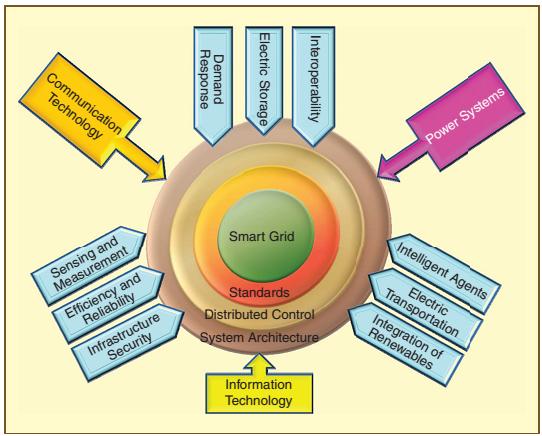
As Figure depicts, the convergence of communication technology and information technology with power system engineering, assisted by an array of new approaches, technologies and applications, allows the existing grid to traverse the complex yet staged trajectory of architecture, protocols, and standards towards the smart grid.
Source:
Hassan Farhangi “The Path of the Smart Grid” IEEE Power & Energy Mazagine. January/February 2010. Pag 18 -28.
Dr. Jorge Luis Mírez Tarrillo
Group of Mathematical Modeling and Numerical Simulation (GMMNS).
Universidad Nacional de Ingeniería. Lima, Perú.
E-mail: jmirez@uni.edu.pe
Website Personal: https://jorgemirez2002.wixsite.com/jorgemirez
Facebook http://www.facebook.com/jorgemirezperu
Linkedin https://www.linkedin.com/in/jorge-luis-mirez-tarrillo-94918423/
Scopus ID: https://www.scopus.com/authid/detail.uri?authorId=56488109800
Google Scholar: https://scholar.google.com/citations?user=_dSpp4YAAAAJ
MATLAB Group Admin in Facebook: https://www.facebook.com/groups/Matlab.Simulink.for.All
WhatsApp Channel/Canal: https://whatsapp.com/channel/0029VbCvpZsAYlUSz2esek2y

The smart grid needs to provide the utility companies with full visibility and pervasive control over their assets and services. The smart grid is required to be self-healing and resilient to system anomalies. And last but not least, the smart grid needs to empower its stakeholders to define and realize new ways of engaging with each other and performing energy transactions across the system. To allow pervasive control and monitoring, the smart grid is emerging as a convergence of information technology and communication technology with power system engineering. Figure depicts the salient features of the smart grid in comparison with the existing grid.
Source:
Hassan Farhangi «The Path of the Smart Grid» IEEE Power & Energy Mazagine. January/February 2010. Pag 18 -28.
Dr. Jorge Luis Mírez Tarrillo
Group of Mathematical Modeling and Numerical Simulation (GMMNS).
Universidad Nacional de Ingeniería. Lima, Perú.
E-mail: jmirez@uni.edu.pe
Website Personal: https://jorgemirez2002.wixsite.com/jorgemirez
Facebook http://www.facebook.com/jorgemirezperu
Linkedin https://www.linkedin.com/in/jorge-luis-mirez-tarrillo-94918423/
Scopus ID: https://www.scopus.com/authid/detail.uri?authorId=56488109800
Google Scholar: https://scholar.google.com/citations?user=_dSpp4YAAAAJ
MATLAB Group Admin in Facebook: https://www.facebook.com/groups/Matlab.Simulink.for.All
WhatsApp Channel/Canal: https://whatsapp.com/channel/0029VbCvpZsAYlUSz2esek2y

Classical HVDC transmission systems [as shown in Figure (a)] are based on the current source converters with naturally commutated thyristors, which are the so-called linecommutated converters (LCCs). This name originates from the fact that the applied thyristors need an ac voltage source in order to commutate and thus only can transfer power between two active ac networks. They are, therefore, less useful in connection with the wind farms as the offshore ac grid needs to be powered up prior to a possible startup. A further disadvantage of LCC-based HVDC transmission systems is the lack of the possibility to provide an independent control of the active and reactive powers. Furthermore, they produce large amounts of harmonics, which make the use of large filters inevitable. Voltage-source converter (VSC)-based HVDC transmission systems are gaining more and more attention not only for the grid connection of large offshore wind farms. Figure (b) shows the schematic of a VSC-based HVDC transmission system
Source:
Juan Manuel Carrasco, Leopoldo García Franquelo, Jan T. Bialasiewicz, Eduardo Galván, Ramón C. Portillo Guisado, Ángeles Martín Prats, José Ignacio León and Narciso Moreno-Alfonso “Power-Electronic Systems for the Grid integration of Renewable Energy Sources: A Survey”. IEEE Transactions on Industrial Electronics, Vol. 53, No. 4, August 2006
Dr. Jorge Luis Mírez Tarrillo
Group of Mathematical Modeling and Numerical Simulation (GMMNS).
Universidad Nacional de Ingeniería. Lima, Perú.
E-mail: jmirez@uni.edu.pe
Website Personal: https://jorgemirez2002.wixsite.com/jorgemirez
Facebook http://www.facebook.com/jorgemirezperu
Linkedin https://www.linkedin.com/in/jorge-luis-mirez-tarrillo-94918423/
Scopus ID: https://www.scopus.com/authid/detail.uri?authorId=56488109800
Google Scholar: https://scholar.google.com/citations?user=_dSpp4YAAAAJ
MATLAB Group Admin in Facebook: https://www.facebook.com/groups/Matlab.Simulink.for.All
WhatsApp Channel/Canal: https://whatsapp.com/channel/0029VbCvpZsAYlUSz2esek2y

This is my simulation made on Matlab/Simulink about difference time of conextion in bank condensers. The reactive power change in the time and it is aleatory. In this context, the mathematical models have that made the emulation of this performance.
Dr. Jorge Luis Mírez Tarrillo
Group of Mathematical Modeling and Numerical Simulation (GMMNS).
Universidad Nacional de Ingeniería. Lima, Perú.
E-mail: jmirez@uni.edu.pe
Website Personal: https://jorgemirez2002.wixsite.com/jorgemirez
Facebook http://www.facebook.com/jorgemirezperu
Linkedin https://www.linkedin.com/in/jorge-luis-mirez-tarrillo-94918423/
Scopus ID: https://www.scopus.com/authid/detail.uri?authorId=56488109800
Google Scholar: https://scholar.google.com/citations?user=_dSpp4YAAAAJ
MATLAB Group Admin in Facebook: https://www.facebook.com/groups/Matlab.Simulink.for.All
WhatsApp Channel/Canal: https://whatsapp.com/channel/0029VbCvpZsAYlUSz2esek2y
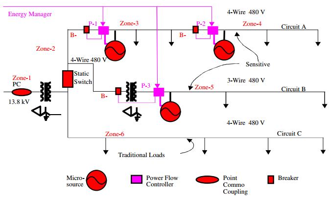
The CERTS Microgrid program has developed control methods to allow the installation of distributed generators (DGs) in commercial and industrial electric power systems in a “plug and play” manner. These control methods allow the generators to be electrically distributed, rather than be installed on the same electrical bus, and do not require intergenerator communications in order to maintain appropriate voltage and frequency at each generator. Note in figure that there is a communication link with the DGs that is labeled “Energy Manager”. This is a conventional energy manager that is used for power dispatch purposes, not for frequency or voltage control. This energy manager can use relatively slow communications links, such as telephone or internet, since it has no bearing on system stability.
Source:
John Stevens «CERTS Microgrid System Test». IEEExplore
Dr. Jorge Luis Mírez Tarrillo
Group of Mathematical Modeling and Numerical Simulation (GMMNS).
Universidad Nacional de Ingeniería. Lima, Perú.
E-mail: jmirez@uni.edu.pe
Website Personal: https://jorgemirez2002.wixsite.com/jorgemirez
Facebook http://www.facebook.com/jorgemirezperu
Linkedin https://www.linkedin.com/in/jorge-luis-mirez-tarrillo-94918423/
Scopus ID: https://www.scopus.com/authid/detail.uri?authorId=56488109800
Google Scholar: https://scholar.google.com/citations?user=_dSpp4YAAAAJ
MATLAB Group Admin in Facebook: https://www.facebook.com/groups/Matlab.Simulink.for.All
WhatsApp Channel/Canal: https://whatsapp.com/channel/0029VbCvpZsAYlUSz2esek2y

The basic philosophy in developing the perfect power system is first to increase the independence, flexibility, and intelligence for optimization of energy use and energy management at the local level; and then to integrate local systems as necessary or justified for deliveringperfect power supply and services.
This path started with the notion that increasingly consumers expect perfection in the end-use devices and appliances they have. Not only does portability enable a highly mobile digital society; but also once perfection in portability is defined, it provides elements of perfection that enable, in turn, a localize perfect system. Localized perfect systems can also accommodate increasing consumer demands for independence, convenience, appearance, environmentally friendly service and cost control.
Local systems can in turn be integrated into distributed perfect systems. Distributed perfect systems can, in turn be interconnected and integrated with technologies that ultimately enable a fully integrated perfect power system. The figure summarizes each of these system configuration stages.
Each of these configurations can essentially be considered a possible structure for the perfect power system in its own right, but each stage logically evolves to the next stage based on the efficiencies, and quality or service value improvements to be attained. In effect, these potential system configuration stages build on each other starting from a portable power system connected to other portable power systems which then can evolve into a building integrated power system, a distributed power system and eventually to a fully integrated power system.
Source:
Clark W. Gellings.The Smart Grid. CRC Press. 2009. ISBN-10 0-88173-623-6
Dr. Jorge Luis Mírez Tarrillo
Group of Mathematical Modeling and Numerical Simulation (GMMNS).
Universidad Nacional de Ingeniería. Lima, Perú.
E-mail: jmirez@uni.edu.pe
Website Personal: https://jorgemirez2002.wixsite.com/jorgemirez
Facebook http://www.facebook.com/jorgemirezperu
Linkedin https://www.linkedin.com/in/jorge-luis-mirez-tarrillo-94918423/
Scopus ID: https://www.scopus.com/authid/detail.uri?authorId=56488109800
Google Scholar: https://scholar.google.com/citations?user=_dSpp4YAAAAJ
MATLAB Group Admin in Facebook: https://www.facebook.com/groups/Matlab.Simulink.for.All
WhatsApp Channel/Canal: https://whatsapp.com/channel/0029VbCvpZsAYlUSz2esek2y

This is a part of my results about interconnected of two microgrids. It have flow power in function a its capacities, but probably a deficit and/or surplus in supply or demand in both microgrids is present. Negative is deficit in microgrid to import from other source different to other microgrid. Positivo is surplus in microgrid by export to other demand different at other microgrid. The figure is a simple example for to show that it is possible using mathematical modelling and simulations on Matlab of MathWork Inc.
Dr. Jorge Luis Mírez Tarrillo
Group of Mathematical Modeling and Numerical Simulation (GMMNS).
Universidad Nacional de Ingeniería. Lima, Perú.
E-mail: jmirez@uni.edu.pe
Website Personal: https://jorgemirez2002.wixsite.com/jorgemirez
Facebook http://www.facebook.com/jorgemirezperu
Linkedin https://www.linkedin.com/in/jorge-luis-mirez-tarrillo-94918423/
Scopus ID: https://www.scopus.com/authid/detail.uri?authorId=56488109800
Google Scholar: https://scholar.google.com/citations?user=_dSpp4YAAAAJ
MATLAB Group Admin in Facebook: https://www.facebook.com/groups/Matlab.Simulink.for.All
WhatsApp Channel/Canal: https://whatsapp.com/channel/0029VbCvpZsAYlUSz2esek2y

This is part of my results in Matlab about power flow between two microgrids interconected. In different color shown the direction of power flow (from Microgrid 1 to Microgrid 2, and from Microgrid 2 to Microgrid 1). The figure is a simple example for to show that it is possible using mathematical modelling and simulations on Matlab of MathWork Inc.
Dr. Jorge Luis Mírez Tarrillo
Group of Mathematical Modeling and Numerical Simulation (GMMNS).
Universidad Nacional de Ingeniería. Lima, Perú.
E-mail: jmirez@uni.edu.pe
Website Personal: https://jorgemirez2002.wixsite.com/jorgemirez
Facebook http://www.facebook.com/jorgemirezperu
Linkedin https://www.linkedin.com/in/jorge-luis-mirez-tarrillo-94918423/
Scopus ID: https://www.scopus.com/authid/detail.uri?authorId=56488109800
Google Scholar: https://scholar.google.com/citations?user=_dSpp4YAAAAJ
MATLAB Group Admin in Facebook: https://www.facebook.com/groups/Matlab.Simulink.for.All
WhatsApp Channel/Canal: https://whatsapp.com/channel/0029VbCvpZsAYlUSz2esek2y

This figure represents the electrical demand in Ecuador. It is noted that during the study period, nearly doubled the demand for electricity. Currently Ecuador already has a transmission line at 500 kV. With technology centers as Yachay, I recommend that Ecuador must bet for the development of technologies such as solar photovoltaics, wind turbines and biomass. Other technologies are possible and with higher added value.
Dr. Jorge Luis Mírez Tarrillo
Group of Mathematical Modeling and Numerical Simulation (GMMNS).
Universidad Nacional de Ingeniería. Lima, Perú.
E-mail: jmirez@uni.edu.pe
Website Personal: https://jorgemirez2002.wixsite.com/jorgemirez
Facebook http://www.facebook.com/jorgemirezperu
Linkedin https://www.linkedin.com/in/jorge-luis-mirez-tarrillo-94918423/
Scopus ID: https://www.scopus.com/authid/detail.uri?authorId=56488109800
Google Scholar: https://scholar.google.com/citations?user=_dSpp4YAAAAJ
MATLAB Group Admin in Facebook: https://www.facebook.com/groups/Matlab.Simulink.for.All
WhatsApp Channel/Canal: https://whatsapp.com/channel/0029VbCvpZsAYlUSz2esek2y

During operation a microgrid, sometimes; renewable energy sources and the external power grid, dispatched electric energy simultaneously. Sometimes, many sources is neccesary for supply to electric load. Also, all it, considering both economic and technical criteria. The figure represent la connection and disconnetion of sources for each state of performance of a microgrid. Too, it is applicable to other similar electric systems.
Dr. Jorge Luis Mírez Tarrillo
Group of Mathematical Modeling and Numerical Simulation (GMMNS).
Universidad Nacional de Ingeniería. Lima, Perú.
E-mail: jmirez@uni.edu.pe
Website Personal: https://jorgemirez2002.wixsite.com/jorgemirez
Facebook http://www.facebook.com/jorgemirezperu
Linkedin https://www.linkedin.com/in/jorge-luis-mirez-tarrillo-94918423/
Scopus ID: https://www.scopus.com/authid/detail.uri?authorId=56488109800
Google Scholar: https://scholar.google.com/citations?user=_dSpp4YAAAAJ
MATLAB Group Admin in Facebook: https://www.facebook.com/groups/Matlab.Simulink.for.All
WhatsApp Channel/Canal: https://whatsapp.com/channel/0029VbCvpZsAYlUSz2esek2y

La figura muestra el concepto de un sistema híbrido ac/dc donde varias fuentes y cargas ac y dc son conectadas a sus correspondientes redes ac y dc. Las redes ac y dc están conectadas a través de dos transformadores y conversores trifásicos ac/dc bidireccionales. Pueden observar la diversidad de micro fuentes que se está utilizando en la descripción de la microred, incluye los diferentes dispositivos de electrónica de potencia que sirven para adecuar la energía eléctrica desde fuentes y para cargas eléctricas. Hay vehículos eléctricos conectados a la microred. Los generadores eólicos tienen diferentes configuración de control (diferentes tipos de turbinas eólicas). Un grupo electrógeno diesel también se da, dado que estos grupos se consideran los que en último caso darán energía a la microred eléctrica en situaciones ya críticas pero a la vez rentables en lo posible en economía. Para todo esto se crea modelos matemáticos de cada elemento y luego se integran en un solo programa en que se puedan cambiar las condiciones de trabajo y analizar las variables de respuesta de lo que se desea estudiar. Yo lo hago en Matlab/Simulink para quienes deseen que les brinde el servicio de asesoramiento.
The information related to this post for sale for US $ 10.00. You can make payments through PayPal account: jorgemirez2002@gmail.com or send an e-mail to receive PayPal invoice and make your payment quickly and easily. Tell us (through e-mail) the name of the input or inputs that interests you. // La información relacionada con este post en venta por US $ 10.00. Usted puede hacer pagos a través de cuenta PayPal: jorgemirez2002@gmail.com o enviar un e-mail para recibir la factura de PayPal y hacer su pago de forma rápida y sencilla. Díganos (por medio de email) el nombre de la entrada o entradas que le interese.
Dr. Jorge Luis Mírez Tarrillo
Group of Mathematical Modeling and Numerical Simulation (GMMNS).
Universidad Nacional de Ingeniería. Lima, Perú.
E-mail: jmirez@uni.edu.pe
Website Personal: https://jorgemirez2002.wixsite.com/jorgemirez
Facebook http://www.facebook.com/jorgemirezperu
Linkedin https://www.linkedin.com/in/jorge-luis-mirez-tarrillo-94918423/
Scopus ID: https://www.scopus.com/authid/detail.uri?authorId=56488109800
Google Scholar: https://scholar.google.com/citations?user=_dSpp4YAAAAJ
MATLAB Group Admin in Facebook: https://www.facebook.com/groups/Matlab.Simulink.for.All
WhatsApp Channel/Canal: https://whatsapp.com/channel/0029VbCvpZsAYlUSz2esek2y

La distorción armónica total de la corriente de salida en el rango de operación de un generador debe ser menor que 5 % de la corriente fundamental. La tabla muestra el valor de los armónicos que no deben exceder esos límites, expresados en relación a la corriente fundamental. Se habla de armónicos pares e impares, interesan todos dado que dependiendo del armónicos los efectos son diferentes, algunos de ellos se les puede reconocer con los cinco sentidos, otros requieren equipos como Analizadores de Redes Eléctricas. Que hacer en lugares con alta distorción armónica?. Una de las formas más fáciles es colocar un transformador de impedancia y un transformador de aislamiento (corregirme si me equivoco). Sin embargo, estas cosas para instalaciones medianas y grandes resultan bastante caras y espaciosas, considerando también las pérdidas asociadas a su funcionamiento. Por lo tanto, como cliente es pararse bien frente a las empresas de electricidad y como autoproductor de electricidad es comprar un buen generador que cumpla las exigencias de calidad de energía eléctrica, de esta manera proteges tu inversión y obtienes una fiabilidad alta y rentabilidad bastante ya que el beneficio es para toda la instalación (máquinas y sistemas de iluminación que en condiciones adecuadas brinda clima laboral adecuado sin flickers y/o baja iluminación).
The information related to this post for sale for US $ 1000.00. You can make payments through PayPal account: jorgemirez2002@gmail.com or send an e-mail to receive PayPal invoice and make your payment quickly and easily. Tell us (through e-mail) the name of the input or inputs that interests you. // La información relacionada con este post en venta por US $ 1000.00. Usted puede hacer pagos a través de cuenta PayPal: jorgemirez2002@gmail.com o enviar un e-mail para recibir la factura de PayPal y hacer su pago de forma rápida y sencilla. Díganos (por medio de email) el nombre de la entrada o entradas que le interese.
Dr. Jorge Luis Mírez Tarrillo
Group of Mathematical Modeling and Numerical Simulation (GMMNS).
Universidad Nacional de Ingeniería. Lima, Perú.
E-mail: jmirez@uni.edu.pe
Website Personal: https://jorgemirez2002.wixsite.com/jorgemirez
Facebook http://www.facebook.com/jorgemirezperu
Linkedin https://www.linkedin.com/in/jorge-luis-mirez-tarrillo-94918423/
Scopus ID: https://www.scopus.com/authid/detail.uri?authorId=56488109800
Google Scholar: https://scholar.google.com/citations?user=_dSpp4YAAAAJ
MATLAB Group Admin in Facebook: https://www.facebook.com/groups/Matlab.Simulink.for.All
WhatsApp Channel/Canal: https://whatsapp.com/channel/0029VbCvpZsAYlUSz2esek2y

Quienes hemos visto como funciona un banco de condensadores, podemos ver y escuchar el conectar y desconectar de los condensadores los cuales se van conectando dependiendo de la necesidad de potencia reactiva a inyectar y de las acciones del sistema de control. En la figura se muestra un ejemplo de funcionamiento de condensador para unos 100 estados o ciclos de trabajo, medida que he usado en esta figura, dado que la necesidad de potencia reactiva no depende de la escala de tiempo, es por lo general aleatoria, entonces lo que puedo ir determinando es si esta en conectado ON o desconectado OFF. Un sistema de ceros y unos sirven para identificar cada estado. La simulación está hecha en Matlab de MathWork Inc y complementa lo que post atrás es la ponencia que realice en Costa Rica durante el III Congreso Iberoamericano de Microredes con Generación Distribuida de Renovables. Favor difundir éste blog y si les interesa mis servicios, me escriben :)D
The information related to this post for sale for US $ 100.00. You can make payments through PayPal account: jorgemirez2002@gmail.com or send an e-mail to receive PayPal invoice and make your payment quickly and easily. Tell us (through e-mail) the name of the input or inputs that interests you. // La información relacionada con este post en venta por US $ 100.00. Usted puede hacer pagos a través de cuenta PayPal: jorgemirez2002@gmail.com o enviar un e-mail para recibir la factura de PayPal y hacer su pago de forma rápida y sencilla. Díganos (por medio de email) el nombre de la entrada o entradas que le interese.
Dr. Jorge Luis Mírez Tarrillo
Group of Mathematical Modeling and Numerical Simulation (GMMNS).
Universidad Nacional de Ingeniería. Lima, Perú.
E-mail: jmirez@uni.edu.pe
Website Personal: https://jorgemirez2002.wixsite.com/jorgemirez
Facebook http://www.facebook.com/jorgemirezperu
Linkedin https://www.linkedin.com/in/jorge-luis-mirez-tarrillo-94918423/
Scopus ID: https://www.scopus.com/authid/detail.uri?authorId=56488109800
Google Scholar: https://scholar.google.com/citations?user=_dSpp4YAAAAJ
MATLAB Group Admin in Facebook: https://www.facebook.com/groups/Matlab.Simulink.for.All
WhatsApp Channel/Canal: https://whatsapp.com/channel/0029VbCvpZsAYlUSz2esek2y

La energía reactiva solicitada por los diferentes dispositivos como motores eléctricos o equipos de electrónica de potencia es para poder funcionar, sin embargo, ocupan espacio dentro de la capacidad de transmisión de los conductores eléctricos, es por ello que hay que reducir dicho flujo a lo necesario que es la potencia activa, sin embargo, no puede ser sólo energía activa, dado que se entrar en una resonancia, pero si bien se puede trabajar en un factor de potencia lo más cercano a 1, pero no tanto que el sistema de control no lo pueda coordinar bien. La figura muestra una simulación del trabajo de un banco de condensadores, se puede apreciar tanto la potencia reactiva solicitada por la red eléctrica como la que brinda el banco de condensadores, ambos lo bastante cercanos que las curvas se parecen suporponer. Hecho en Matlab de MathWorks Inc para todos los interesados en los sistemas eléctricos y en el manejo adecuado del factor de potencia.
The information related to this post for sale for US $ 100.00. You can make payments through PayPal account: jorgemirez2002@gmail.com or send an e-mail to receive PayPal invoice and make your payment quickly and easily. Tell us (through e-mail) the name of the input or inputs that interests you. // La información relacionada con este post en venta por US $ 100.00. Usted puede hacer pagos a través de cuenta PayPal: jorgemirez2002@gmail.com o enviar un e-mail para recibir la factura de PayPal y hacer su pago de forma rápida y sencilla. Díganos (por medio de email) el nombre de la entrada o entradas que le interese.
Dr. Jorge Luis Mírez Tarrillo
Group of Mathematical Modeling and Numerical Simulation (GMMNS).
Universidad Nacional de Ingeniería. Lima, Perú.
E-mail: jmirez@uni.edu.pe
Website Personal: https://jorgemirez2002.wixsite.com/jorgemirez
Facebook http://www.facebook.com/jorgemirezperu
Linkedin https://www.linkedin.com/in/jorge-luis-mirez-tarrillo-94918423/
Scopus ID: https://www.scopus.com/authid/detail.uri?authorId=56488109800
Google Scholar: https://scholar.google.com/citations?user=_dSpp4YAAAAJ
MATLAB Group Admin in Facebook: https://www.facebook.com/groups/Matlab.Simulink.for.All
WhatsApp Channel/Canal: https://whatsapp.com/channel/0029VbCvpZsAYlUSz2esek2y

Cualquier consumidor de energía eléctrica va a tener una potencia activa y reactiva que absolver y estas por lo general son proporcionales, debido a que el factor de potencia derivado del ajuste hecho por el banco de condensadores tratan de mantenerlo en proporción constante. Sin embargo, cuando se tiene una microred con fuentes propias o un usuario y a la vez conectado a la red eléctrica pública, pueda que en ciertos momentos haya un cierto flujo de potencia activa y/o reactiva hacia la red. Por lo general, es la reactiva, dado que las potencias de las fuentes se hacen siempre un poco menor a las necesidades y las condiciones ambientales también lo propician, además, hay regulación de en algunos países que no quieren que se inyecte a la red la potencia activa, pero de la reactiva no dicen nada, obvio, la inyección de potencia reactiva hacia la red pública de electricidad les ayuda a compensar el factor de potencia usando los bancos de condensadores de la microred. La simulación presentada en la figura ha sido hecha en Matlab de MathWork Inc. y sirve para visualizar como en momentos (se muestra valores absolutos) la potencia activa y/o reactiva toma diferentes direcciones (hacia o desde la red pública de electricidad). Espero os sirva.
The information related to this post for sale for US $ 20.00. You can make payments through PayPal account: jorgemirez2002@gmail.com or send an e-mail to receive PayPal invoice and make your payment quickly and easily. Tell us (through e-mail) the name of the input or inputs that interests you. // La información relacionada con este post en venta por US $ 20.00. Usted puede hacer pagos a través de cuenta PayPal: jorgemirez2002@gmail.com o enviar un e-mail para recibir la factura de PayPal y hacer su pago de forma rápida y sencilla. Díganos (por medio de email) el nombre de la entrada o entradas que le interese.
Dr. Jorge Luis Mírez Tarrillo
Group of Mathematical Modeling and Numerical Simulation (GMMNS).
Universidad Nacional de Ingeniería. Lima, Perú.
E-mail: jmirez@uni.edu.pe
Website Personal: https://jorgemirez2002.wixsite.com/jorgemirez
Facebook http://www.facebook.com/jorgemirezperu
Linkedin https://www.linkedin.com/in/jorge-luis-mirez-tarrillo-94918423/
Scopus ID: https://www.scopus.com/authid/detail.uri?authorId=56488109800
Google Scholar: https://scholar.google.com/citations?user=_dSpp4YAAAAJ
MATLAB Group Admin in Facebook: https://www.facebook.com/groups/Matlab.Simulink.for.All
WhatsApp Channel/Canal: https://whatsapp.com/channel/0029VbCvpZsAYlUSz2esek2y
Blog in ENGLISH

Compra/Buy – Haz una donación/Make a donation

Dear reader, if you wish to make a donation or are interested in any information or code, please contact me (e-mail: jmirez@uni.edu.pe). Donations will allow you to continue studying and researching, and also to provide more information on this blog. My PayPal account is jorgemirez2002@gmail.com or if it is by bank transfer write to my email jmirez@uni.edu.pe. Any amount of money is welcome. Thank you.
Estimado lector, si desean hacer una donación o le interesa alguna información o código, favor ponerse en contacto con mi persona (e-mail: jmirez@uni.edu.pe). Las donaciones va a permitir seguir estudiando e investigando, y además, el poder brindar más información en este blog. Mi cuenta en PayPal es jorgemirez2002@gmail.com o si es por transferencia bancaria escribirme a mi correo jmirez@uni.edu.pe. Cualquier cantidad de dinero es bienvenido. Gracias.
Datos Generales
Good day. My full name is Jorge Luis MIREZ TARRILLO.
I am Peruvian and live in Lima, capital of Perú in South America.I am Mechanical Electrical Engineering, MSc Physics and Dr. Physics (title doctoral thesis: Control, Optimization, and Management of Microgrid Current Direct)
Too, actually job as Principal Professor in Faculty of Oil, Gas and Petrochemical Engineering of Universidad Nacional de Ingeniería (National University of Engineering) in Lima – PERU (Courses: Modern Physics, Differential Equations and Research's Methodology)
My subjects of my interest are control, signal processing, optimization, simulation, biomedical research, smart grid, microgrid, water.
I have experience in Matlab/Simulink programming, biomedical equipment, electrical systems, renewable energies, microgrids, saturated steam systems 100 psi and organizing academic events.

Comentarios Recientes
Elementos que compon… en J506: Los elementos de un paqu… Dr. Jorge Mírez en Message by IEEE Community Dr. Jorge Mírez en J546: Simulación de campos mag… jose luis huayanay v… en Message by IEEE Community Cesar Aviles en J546: Simulación de campos mag… Dr. Jorge Mírez en J518: La herramienta pdetool d… Dr. Jorge Mírez en J496: Simulación en Matlab/Sim… Raúl Barrios Elizarr… en J496: Simulación en Matlab/Sim… jose luis huayanay v… en J518: La herramienta pdetool d… MSc. Jorge Mírez en J281: La Rosa de Vientos: Frec…


Debe estar conectado para enviar un comentario.