Archive for the ‘Wind Power’ Category

The use of low-speed permanent-magnet generators that have a large number of poles allows obtaining the dc sources from the multiple wounds of this electrical machine, as can be seen in Figure. In this case, the power-electronic building block (PEBB) can be composed of a rectifier, a dc link, and an H-bridge. Another possibility is to replace the rectifier by an additional H-bridge. The continuous reduction of the cost per kilowatt of PEBBs is making the multilevel cascaded topologies to be the most commonly used by the industrial solutions. This as one alternative to multinivel conversors.
Source:
Juan Manuel Carrasco, Leopoldo García Franquelo, Jan T. Bialasiewicz, Eduardo Galván, Ramón C. Portillo Guisado, Ángeles Martín Prats, José Ignacio León and Narciso Moreno-Alfonso “Power-Electronic Systems for the Grid integration of Renewable Energy Sources: A Survey”. IEEE Transactions on Industrial Electronics, Vol. 53, No. 4, August 2006
Dr. Jorge Luis Mírez Tarrillo
Group of Mathematical Modeling and Numerical Simulation (GMMNS).
Universidad Nacional de Ingeniería. Lima, Perú.
E-mail: jmirez@uni.edu.pe
Website Personal: https://jorgemirez2002.wixsite.com/jorgemirez
Facebook http://www.facebook.com/jorgemirezperu
Linkedin https://www.linkedin.com/in/jorge-luis-mirez-tarrillo-94918423/
Scopus ID: https://www.scopus.com/authid/detail.uri?authorId=56488109800
Google Scholar: https://scholar.google.com/citations?user=_dSpp4YAAAAJ
MATLAB Group Admin in Facebook: https://www.facebook.com/groups/Matlab.Simulink.for.All
WhatsApp Channel/Canal: https://whatsapp.com/channel/0029VbCvpZsAYlUSz2esek2y

Classical HVDC transmission systems [as shown in Figure (a)] are based on the current source converters with naturally commutated thyristors, which are the so-called linecommutated converters (LCCs). This name originates from the fact that the applied thyristors need an ac voltage source in order to commutate and thus only can transfer power between two active ac networks. They are, therefore, less useful in connection with the wind farms as the offshore ac grid needs to be powered up prior to a possible startup. A further disadvantage of LCC-based HVDC transmission systems is the lack of the possibility to provide an independent control of the active and reactive powers. Furthermore, they produce large amounts of harmonics, which make the use of large filters inevitable. Voltage-source converter (VSC)-based HVDC transmission systems are gaining more and more attention not only for the grid connection of large offshore wind farms. Figure (b) shows the schematic of a VSC-based HVDC transmission system
Source:
Juan Manuel Carrasco, Leopoldo García Franquelo, Jan T. Bialasiewicz, Eduardo Galván, Ramón C. Portillo Guisado, Ángeles Martín Prats, José Ignacio León and Narciso Moreno-Alfonso “Power-Electronic Systems for the Grid integration of Renewable Energy Sources: A Survey”. IEEE Transactions on Industrial Electronics, Vol. 53, No. 4, August 2006
Dr. Jorge Luis Mírez Tarrillo
Group of Mathematical Modeling and Numerical Simulation (GMMNS).
Universidad Nacional de Ingeniería. Lima, Perú.
E-mail: jmirez@uni.edu.pe
Website Personal: https://jorgemirez2002.wixsite.com/jorgemirez
Facebook http://www.facebook.com/jorgemirezperu
Linkedin https://www.linkedin.com/in/jorge-luis-mirez-tarrillo-94918423/
Scopus ID: https://www.scopus.com/authid/detail.uri?authorId=56488109800
Google Scholar: https://scholar.google.com/citations?user=_dSpp4YAAAAJ
MATLAB Group Admin in Facebook: https://www.facebook.com/groups/Matlab.Simulink.for.All
WhatsApp Channel/Canal: https://whatsapp.com/channel/0029VbCvpZsAYlUSz2esek2y

The figure shows the scheme of a full power converter for a wind turbine. The machine-side three-phase converter works as a driver controlling the torque generator, using a vector control strategy. The grid-side three-phase converter permits windenergy transfer into the grid and enables to control the amount of the active and reactive powers delivered to the grid. It also keeps the total-harmonic-distortion (THD) coefficient as low as possible, improving the quality of the energy injected into the public grid. The induction generator of wind turbine is connected to a voltage-source inverter (VSI) used as a rectifier
Source:
Juan Manuel Carrasco, Leopoldo García Franquelo, Jan T. Bialasiewicz, Eduardo Galván, Ramón C. Portillo Guisado, Ángeles Martín Prats, José Ignacio León and Narciso Moreno-Alfonso “Power-Electronic Systems for the Grid integration of Renewable Energy Sources: A Survey”. IEEE Transactions on Industrial Electronics, Vol. 53, No. 4, August 2006
Dr. Jorge Luis Mírez Tarrillo
Group of Mathematical Modeling and Numerical Simulation (GMMNS).
Universidad Nacional de Ingeniería. Lima, Perú.
E-mail: jmirez@uni.edu.pe
Website Personal: https://jorgemirez2002.wixsite.com/jorgemirez
Facebook http://www.facebook.com/jorgemirezperu
Linkedin https://www.linkedin.com/in/jorge-luis-mirez-tarrillo-94918423/
Scopus ID: https://www.scopus.com/authid/detail.uri?authorId=56488109800
Google Scholar: https://scholar.google.com/citations?user=_dSpp4YAAAAJ
MATLAB Group Admin in Facebook: https://www.facebook.com/groups/Matlab.Simulink.for.All
WhatsApp Channel/Canal: https://whatsapp.com/channel/0029VbCvpZsAYlUSz2esek2y

A number of turbines, ranging from 600 kW to 2.75 MW, have the variable-speed conditions are achieved dissipating the energy within a resistor placed in the rotor, as shown in Figure. Using that technology, the efficiency of the system decreases when the slip increases, and the speed control is limited to a narrow margin. This scheme includes the power converter and the resistors in the rotor. Trigger signals to the power switches are accomplished by optical coupling
Source:
Juan Manuel Carrasco, Leopoldo García Franquelo, Jan T. Bialasiewicz, Eduardo Galván, Ramón C. Portillo Guisado, Ángeles Martín Prats, José Ignacio León and Narciso Moreno-Alfonso “Power-Electronic Systems for the Grid integration of Renewable Energy Sources: A Survey”. IEEE Transactions on Industrial Electronics, Vol. 53, No. 4, August 2006
Dr. Jorge Luis Mírez Tarrillo
Group of Mathematical Modeling and Numerical Simulation (GMMNS).
Universidad Nacional de Ingeniería. Lima, Perú.
E-mail: jmirez@uni.edu.pe
Website Personal: https://jorgemirez2002.wixsite.com/jorgemirez
Facebook http://www.facebook.com/jorgemirezperu
Linkedin https://www.linkedin.com/in/jorge-luis-mirez-tarrillo-94918423/
Scopus ID: https://www.scopus.com/authid/detail.uri?authorId=56488109800
Google Scholar: https://scholar.google.com/citations?user=_dSpp4YAAAAJ
MATLAB Group Admin in Facebook: https://www.facebook.com/groups/Matlab.Simulink.for.All
WhatsApp Channel/Canal: https://whatsapp.com/channel/0029VbCvpZsAYlUSz2esek2y

Variable-Speed Concept Utilizing Doubly Fed Induction Generator (DFIG):In a variable-speed turbine with DFIG, the converter feeds the rotor winding, while the stator winding is connected directly to the grid. This converter, thus decoupling mechanical and electrical frequencies and making variable-speed operation possible, can vary the electrical rotor frequency. This turbine cannot operate in the full range from zero to the rated speed, but the speed range is quite sufficient. This limited speed range is caused by the fact that a converter that is considerably smaller than the rated power of the machine is used. In principle, one can say that the ratio between the size of the converter and the wind-turbine rating is half of the rotor-speed span. In addition to the fact that the converter is smaller, the losses are also lower. The control possibilities of the reactive power are similar to the full power-converter system. For instance, the Spanish company Gamesa supplies this kind of variable-speed wind turbines to the market. The forced switched power-converter scheme is shown in Figure. The converter includes two three-phase ac–dc converters linked by a dc capacitor battery. This scheme allows, on one hand, a vector control of the active and reactive powers of the machine, and on the other hand, a decrease by a high percentage of the harmonic content injected into the grid by the power converter.
Source:
Juan Manuel Carrasco, Leopoldo García Franquelo, Jan T. Bialasiewicz, Eduardo Galván, Ramón C. Portillo Guisado, Ángeles Martín Prats, José Ignacio León and Narciso Moreno-Alfonso «Power-Electronic Systems for the Grid integration of Renewable Energy Sources: A Survey». IEEE Transactions on Industrial Electronics, Vol. 53, No. 4, August 2006
Dr. Jorge Luis Mírez Tarrillo
Group of Mathematical Modeling and Numerical Simulation (GMMNS).
Universidad Nacional de Ingeniería. Lima, Perú.
E-mail: jmirez@uni.edu.pe
Website Personal: https://jorgemirez2002.wixsite.com/jorgemirez
Facebook http://www.facebook.com/jorgemirezperu
Linkedin https://www.linkedin.com/in/jorge-luis-mirez-tarrillo-94918423/
Scopus ID: https://www.scopus.com/authid/detail.uri?authorId=56488109800
Google Scholar: https://scholar.google.com/citations?user=_dSpp4YAAAAJ
MATLAB Group Admin in Facebook: https://www.facebook.com/groups/Matlab.Simulink.for.All
WhatsApp Channel/Canal: https://whatsapp.com/channel/0029VbCvpZsAYlUSz2esek2y
J963e: Other example of microgrid con cell fuel wind turbine PV microturbine battery bank and loads…

This microgrid have different elements: wind turbine, photovoltaics, fuel cell, battery bank, microturbine and interconection with main grifd. The level power is little but it is a interesting microgrid for study. It is a typical AC microgrid with load distribuited in many locations into microgrid. Main grind is a sub-transmission network in 20 kV.
Image Source:
Aris L. Dimeas, Nikos D. Natziargyriou “Operation of Multiagent System for Microgrid Control” IEEE Transactions on Power Systems, Vol. 20, No. 3, August 2005.
Dr. Jorge Luis Mírez Tarrillo
Group of Mathematical Modeling and Numerical Simulation (GMMNS).
Universidad Nacional de Ingeniería. Lima, Perú.
E-mail: jmirez@uni.edu.pe
Website Personal: https://jorgemirez2002.wixsite.com/jorgemirez
Facebook http://www.facebook.com/jorgemirezperu
Linkedin https://www.linkedin.com/in/jorge-luis-mirez-tarrillo-94918423/
Scopus ID: https://www.scopus.com/authid/detail.uri?authorId=56488109800
Google Scholar: https://scholar.google.com/citations?user=_dSpp4YAAAAJ
MATLAB Group Admin in Facebook: https://www.facebook.com/groups/Matlab.Simulink.for.All
WhatsApp Channel/Canal: https://whatsapp.com/channel/0029VbCvpZsAYlUSz2esek2y

Sun –> energy provided from photovoltaic energy plant.
Wind –> similar from wind turbine(s)
Batt –> similar from battery bank
ene –> similar injected from electrical network external or utility electric network
In other image in red is the total suministed for this sources and red line is the demand. Other images is cost, evoluction of energy supply from each source and more details. It is made for me (Jorge Mírez) in Matlabb/Simulink and I utilized concept of linear programming. Image is from my destokp laptop.
Dr. Jorge Luis Mírez Tarrillo
Group of Mathematical Modeling and Numerical Simulation (GMMNS).
Universidad Nacional de Ingeniería. Lima, Perú.
E-mail: jmirez@uni.edu.pe
Website Personal: https://jorgemirez2002.wixsite.com/jorgemirez
Facebook http://www.facebook.com/jorgemirezperu
Linkedin https://www.linkedin.com/in/jorge-luis-mirez-tarrillo-94918423/
Scopus ID: https://www.scopus.com/authid/detail.uri?authorId=56488109800
Google Scholar: https://scholar.google.com/citations?user=_dSpp4YAAAAJ
MATLAB Group Admin in Facebook: https://www.facebook.com/groups/Matlab.Simulink.for.All
WhatsApp Channel/Canal: https://whatsapp.com/channel/0029VbCvpZsAYlUSz2esek2y

El block diagram structure of a microgrid is shown in Figure. The main task of the power plant’s power electronic converter is to fit primary energy converter’s output voltage to the microgrid power line voltage, and source operating point control as well as low and high level microgrid’s control. The converter’s structure depends on a type of primary energy converter. A common feature of the converters concerns their output current. It should be permanent and low ripple.
Source:
Piotr Biczel. “Power Electronic Converters in DC Microgrid”. IEEE 5th International Conference – Workshop, Compatibility in Power Electronics, CPE 2007. Poland.
Dr. Jorge Luis Mírez Tarrillo
Group of Mathematical Modeling and Numerical Simulation (GMMNS).
Universidad Nacional de Ingeniería. Lima, Perú.
E-mail: jmirez@uni.edu.pe
Website Personal: https://jorgemirez2002.wixsite.com/jorgemirez
Facebook http://www.facebook.com/jorgemirezperu
Linkedin https://www.linkedin.com/in/jorge-luis-mirez-tarrillo-94918423/
Scopus ID: https://www.scopus.com/authid/detail.uri?authorId=56488109800
Google Scholar: https://scholar.google.com/citations?user=_dSpp4YAAAAJ
MATLAB Group Admin in Facebook: https://www.facebook.com/groups/Matlab.Simulink.for.All
WhatsApp Channel/Canal: https://whatsapp.com/channel/0029VbCvpZsAYlUSz2esek2y

This a typical scheme of a microgrid AC/DC. It maybe contain many technologies as micro-source, storage, loads and monitoring and control. Un Microgrid Bus linked the different components.
Source:
N. R. Rahmanov, N. M. Tabatabaei, K. Dursun, O. Z. Kerimov. «Combined AC-DC Microgrids: Case Study – Network Development and Simulation» International Journal on Technical and Physical Problems of Engineering. September 2012, Issue 12, Volume 4, Number 3, Pages 157 – 161.
Dr. Jorge Luis Mírez Tarrillo
Group of Mathematical Modeling and Numerical Simulation (GMMNS).
Universidad Nacional de Ingeniería. Lima, Perú.
E-mail: jmirez@uni.edu.pe
Website Personal: https://jorgemirez2002.wixsite.com/jorgemirez
Facebook http://www.facebook.com/jorgemirezperu
Linkedin https://www.linkedin.com/in/jorge-luis-mirez-tarrillo-94918423/
Scopus ID: https://www.scopus.com/authid/detail.uri?authorId=56488109800
Google Scholar: https://scholar.google.com/citations?user=_dSpp4YAAAAJ
MATLAB Group Admin in Facebook: https://www.facebook.com/groups/Matlab.Simulink.for.All
WhatsApp Channel/Canal: https://whatsapp.com/channel/0029VbCvpZsAYlUSz2esek2y

The dc microgrid considered is schematically shown in Fig. As for a typical dc microgrid, it consists of the following mainelements:
• variable (nondeterministic) generations and, in this example, a wind turbine using permanent-magnet synchronous generator (PMSG); the maximum power output from the wind turbine is largely determined by the wind condition;
• controlled (deterministic) generation (e.g., a diesel generator or with ac grid connection); as shown in Fig, the dc grid in this example is connected to an external ac system via a dc-ac converter which provides bidirectionalpower-flow capability;
• variable loads with different characteristics; a number of ac and dc loads can be anticipated (e.g., ac loads via dc-ac inverters, dc loads via dc-dc converters, and direct-connected dc loads, etc.);
• energy storage (ES) system to accommodate the presence of variable generation and load, and the requirement of possible island operation (i.e., connection to the external ac system being lost)
Reference:
Lie Xu, Dong Chen. “Control and Operation of a DC Microgrid With Variable Generation and Energy Storage”. IEEE Transactions on Power Delivery, Vol. 26, No. 4, October 2011
Dr. Jorge Luis Mírez Tarrillo
Group of Mathematical Modeling and Numerical Simulation (GMMNS).
Universidad Nacional de Ingeniería. Lima, Perú.
E-mail: jmirez@uni.edu.pe
Website Personal: https://jorgemirez2002.wixsite.com/jorgemirez
Facebook http://www.facebook.com/jorgemirezperu
Linkedin https://www.linkedin.com/in/jorge-luis-mirez-tarrillo-94918423/
Scopus ID: https://www.scopus.com/authid/detail.uri?authorId=56488109800
Google Scholar: https://scholar.google.com/citations?user=_dSpp4YAAAAJ
MATLAB Group Admin in Facebook: https://www.facebook.com/groups/Matlab.Simulink.for.All
WhatsApp Channel/Canal: https://whatsapp.com/channel/0029VbCvpZsAYlUSz2esek2y

This simulation is about microgrid with solar and wind source, battery storage and utility network. It have cost differents and the simulation is para 96 time’s step. The distance between time’s step is configurable and it depend of characteristic of each source and all source in general. Made on Matlab of Math/Works Inc.
Dr. Jorge Luis Mírez Tarrillo
Group of Mathematical Modeling and Numerical Simulation (GMMNS).
Universidad Nacional de Ingeniería. Lima, Perú.
E-mail: jmirez@uni.edu.pe
Website Personal: https://jorgemirez2002.wixsite.com/jorgemirez
Facebook http://www.facebook.com/jorgemirezperu
Linkedin https://www.linkedin.com/in/jorge-luis-mirez-tarrillo-94918423/
Scopus ID: https://www.scopus.com/authid/detail.uri?authorId=56488109800
Google Scholar: https://scholar.google.com/citations?user=_dSpp4YAAAAJ
MATLAB Group Admin in Facebook: https://www.facebook.com/groups/Matlab.Simulink.for.All
WhatsApp Channel/Canal: https://whatsapp.com/channel/0029VbCvpZsAYlUSz2esek2y

During operation a microgrid, sometimes; renewable energy sources and the external power grid, dispatched electric energy simultaneously. Sometimes, many sources is neccesary for supply to electric load. Also, all it, considering both economic and technical criteria. The figure represent la connection and disconnetion of sources for each state of performance of a microgrid. Too, it is applicable to other similar electric systems.
Dr. Jorge Luis Mírez Tarrillo
Group of Mathematical Modeling and Numerical Simulation (GMMNS).
Universidad Nacional de Ingeniería. Lima, Perú.
E-mail: jmirez@uni.edu.pe
Website Personal: https://jorgemirez2002.wixsite.com/jorgemirez
Facebook http://www.facebook.com/jorgemirezperu
Linkedin https://www.linkedin.com/in/jorge-luis-mirez-tarrillo-94918423/
Scopus ID: https://www.scopus.com/authid/detail.uri?authorId=56488109800
Google Scholar: https://scholar.google.com/citations?user=_dSpp4YAAAAJ
MATLAB Group Admin in Facebook: https://www.facebook.com/groups/Matlab.Simulink.for.All
WhatsApp Channel/Canal: https://whatsapp.com/channel/0029VbCvpZsAYlUSz2esek2y

In a microgrid, each energy source is required according to the criterion of costs and production capacity. During the operation time, accumulative energy from each source is represented in the figure. Criteria of linear optimization has been used in this modelling and simulation. This allows determining the nominal capacity and the ability to respond to sudden requests. Made on Matlab of MathWorks Inc.
Dr. Jorge Luis Mírez Tarrillo
Group of Mathematical Modeling and Numerical Simulation (GMMNS).
Universidad Nacional de Ingeniería. Lima, Perú.
E-mail: jmirez@uni.edu.pe
Website Personal: https://jorgemirez2002.wixsite.com/jorgemirez
Facebook http://www.facebook.com/jorgemirezperu
Linkedin https://www.linkedin.com/in/jorge-luis-mirez-tarrillo-94918423/
Scopus ID: https://www.scopus.com/authid/detail.uri?authorId=56488109800
Google Scholar: https://scholar.google.com/citations?user=_dSpp4YAAAAJ
MATLAB Group Admin in Facebook: https://www.facebook.com/groups/Matlab.Simulink.for.All
WhatsApp Channel/Canal: https://whatsapp.com/channel/0029VbCvpZsAYlUSz2esek2y

One of the most promising applications of renewable energy technology is the installation of hybrid
energy systems (HES) in remote areas, where the grid extension is costly and the cost of fuel increases drastically with the remoteness of the location. Recent research have shown that HES have an excellent potential, as a form of supplementary contribution to conventional power generation systems. In figure, one of the most common hybrid renewable system implemented and studied is described.
Source:
Francisco Goncalves Goina Mesquita. «Design Optimization of Stand-Alone Hybrid Energy Systems». A Dissertation submitted under the scope of Mestrado Integrado em Engenharia Electrotécnica e de Computadores Major Energia. Fevereiro de 2010. Facultade de Engenharia da Universidade do Porto.
Dr. Jorge Luis Mírez Tarrillo
Group of Mathematical Modeling and Numerical Simulation (GMMNS).
Universidad Nacional de Ingeniería. Lima, Perú.
E-mail: jmirez@uni.edu.pe
Website Personal: https://jorgemirez2002.wixsite.com/jorgemirez
Facebook http://www.facebook.com/jorgemirezperu
Linkedin https://www.linkedin.com/in/jorge-luis-mirez-tarrillo-94918423/
Scopus ID: https://www.scopus.com/authid/detail.uri?authorId=56488109800
Google Scholar: https://scholar.google.com/citations?user=_dSpp4YAAAAJ
MATLAB Group Admin in Facebook: https://www.facebook.com/groups/Matlab.Simulink.for.All
WhatsApp Channel/Canal: https://whatsapp.com/channel/0029VbCvpZsAYlUSz2esek2y
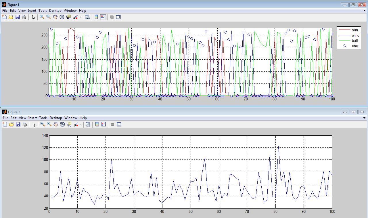
Usually the microgrid used wind turbine (wind), PV (sun), battery (batt) and load, aditional it have a PCC with electrical network external (ene). Both the technical operation as the economic operation are important during performance microgrid. In the figure I show the results of optimization process with imaginary energy prices from diferent source mentioned. In top figure is the power distribution between sources and down figure the total cost of each state. Programming linear has been used in this modelling and simulations.
Dr. Jorge Luis Mírez Tarrillo
Group of Mathematical Modeling and Numerical Simulation (GMMNS).
Universidad Nacional de Ingeniería. Lima, Perú.
E-mail: jmirez@uni.edu.pe
Website Personal: https://jorgemirez2002.wixsite.com/jorgemirez
Facebook http://www.facebook.com/jorgemirezperu
Linkedin https://www.linkedin.com/in/jorge-luis-mirez-tarrillo-94918423/
Scopus ID: https://www.scopus.com/authid/detail.uri?authorId=56488109800
Google Scholar: https://scholar.google.com/citations?user=_dSpp4YAAAAJ
MATLAB Group Admin in Facebook: https://www.facebook.com/groups/Matlab.Simulink.for.All
WhatsApp Channel/Canal: https://whatsapp.com/channel/0029VbCvpZsAYlUSz2esek2y

This is the results of the mathematic modeling and numerical simulation of a wind turbine of 100 kW capacity nominal. The attack angle is optimized for best catch of energy contain in the wind, with it, power coefficient is modified. The speed range of this simulation is from 0 to 25 m/s, with start speed in 4 m/s.
The information related to this post (including *mdl archive Matlab/Simulink and enviromental data) sale for US $ 1000.00. You can make payments through PayPal account: jorgemirez2002@gmail.com or send an e-mail to receive PayPal invoice and make your payment quickly and easily. Tell us (through e-mail) the name of the post or other pots of your interest.
Dr. Jorge Luis Mírez Tarrillo
Group of Mathematical Modeling and Numerical Simulation (GMMNS).
Universidad Nacional de Ingeniería. Lima, Perú.
E-mail: jmirez@uni.edu.pe
Website Personal: https://jorgemirez2002.wixsite.com/jorgemirez
Facebook http://www.facebook.com/jorgemirezperu
Linkedin https://www.linkedin.com/in/jorge-luis-mirez-tarrillo-94918423/
Scopus ID: https://www.scopus.com/authid/detail.uri?authorId=56488109800
Google Scholar: https://scholar.google.com/citations?user=_dSpp4YAAAAJ
MATLAB Group Admin in Facebook: https://www.facebook.com/groups/Matlab.Simulink.for.All
WhatsApp Channel/Canal: https://whatsapp.com/channel/0029VbCvpZsAYlUSz2esek2y

The present post describe the charge and discharge process of a battery bank of a microgrid. This microgrid have a aleatory voltage with inferior and superior limit. The current and electric power of charge and discharge is in picture. This simulation has writing and processing on Matlab/Simulink of MathaWorth Inc. Actually my interest is the control, optimization and management of microgrid DC. Greetings from Perú.
The information related to this post for sale for US $ 1000.00. You can make payments through PayPal account: jorgemirez2002@gmail.com or send an e-mail to receive PayPal invoice and make your payment quickly and easily. Tell us (through e-mail) the name of the input or inputs that interests you. // La información relacionada con este post en venta por US $ 1000.00. Usted puede hacer pagos a través de cuenta PayPal: jorgemirez2002@gmail.com o enviar un e-mail para recibir la factura de PayPal y hacer su pago de forma rápida y sencilla. Díganos (por medio de email) el nombre de la entrada o entradas que le interese.
Dr. Jorge Luis Mírez Tarrillo
Group of Mathematical Modeling and Numerical Simulation (GMMNS).
Universidad Nacional de Ingeniería. Lima, Perú.
E-mail: jmirez@uni.edu.pe
Website Personal: https://jorgemirez2002.wixsite.com/jorgemirez
Facebook http://www.facebook.com/jorgemirezperu
Linkedin https://www.linkedin.com/in/jorge-luis-mirez-tarrillo-94918423/
Scopus ID: https://www.scopus.com/authid/detail.uri?authorId=56488109800
Google Scholar: https://scholar.google.com/citations?user=_dSpp4YAAAAJ
MATLAB Group Admin in Facebook: https://www.facebook.com/groups/Matlab.Simulink.for.All
WhatsApp Channel/Canal: https://whatsapp.com/channel/0029VbCvpZsAYlUSz2esek2y

La figura muestra el concepto de un sistema híbrido ac/dc donde varias fuentes y cargas ac y dc son conectadas a sus correspondientes redes ac y dc. Las redes ac y dc están conectadas a través de dos transformadores y conversores trifásicos ac/dc bidireccionales. Pueden observar la diversidad de micro fuentes que se está utilizando en la descripción de la microred, incluye los diferentes dispositivos de electrónica de potencia que sirven para adecuar la energía eléctrica desde fuentes y para cargas eléctricas. Hay vehículos eléctricos conectados a la microred. Los generadores eólicos tienen diferentes configuración de control (diferentes tipos de turbinas eólicas). Un grupo electrógeno diesel también se da, dado que estos grupos se consideran los que en último caso darán energía a la microred eléctrica en situaciones ya críticas pero a la vez rentables en lo posible en economía. Para todo esto se crea modelos matemáticos de cada elemento y luego se integran en un solo programa en que se puedan cambiar las condiciones de trabajo y analizar las variables de respuesta de lo que se desea estudiar. Yo lo hago en Matlab/Simulink para quienes deseen que les brinde el servicio de asesoramiento.
The information related to this post for sale for US $ 10.00. You can make payments through PayPal account: jorgemirez2002@gmail.com or send an e-mail to receive PayPal invoice and make your payment quickly and easily. Tell us (through e-mail) the name of the input or inputs that interests you. // La información relacionada con este post en venta por US $ 10.00. Usted puede hacer pagos a través de cuenta PayPal: jorgemirez2002@gmail.com o enviar un e-mail para recibir la factura de PayPal y hacer su pago de forma rápida y sencilla. Díganos (por medio de email) el nombre de la entrada o entradas que le interese.
Dr. Jorge Luis Mírez Tarrillo
Group of Mathematical Modeling and Numerical Simulation (GMMNS).
Universidad Nacional de Ingeniería. Lima, Perú.
E-mail: jmirez@uni.edu.pe
Website Personal: https://jorgemirez2002.wixsite.com/jorgemirez
Facebook http://www.facebook.com/jorgemirezperu
Linkedin https://www.linkedin.com/in/jorge-luis-mirez-tarrillo-94918423/
Scopus ID: https://www.scopus.com/authid/detail.uri?authorId=56488109800
Google Scholar: https://scholar.google.com/citations?user=_dSpp4YAAAAJ
MATLAB Group Admin in Facebook: https://www.facebook.com/groups/Matlab.Simulink.for.All
WhatsApp Channel/Canal: https://whatsapp.com/channel/0029VbCvpZsAYlUSz2esek2y

En este post muestro la portada de tesis «Implementación de un Sistema de Generación Distribuida con Energías Renovables ENDE Corporación» elaborado por Mario Torrico para la Universidad Privada del Valle en Cochabamba – Bolivia para optar el título de Ingeniero Electromecánico. Trabajo que compartimos durante unos tres meses de intercambio de información, modelos matemáticos y simulaciones numéricas, además de diálogo, envío de información, debate y varios borradores de tesis que iban y venían en el correo electrónico. Su defensa fue un éxito alcanzando la nota de 90/100 para alegría de Mario, de su familia, profesores, colegas y amigos. Éxitos Mario en tu vida profesional, tengo un colega amigo más :)D . En lo personal el tema fue muy interesante e implicó ingresar en una temática no desarrollada e innovadora… la portada de la tesis esta bonita también. Saludos a la plurinación boliviana… A quienes desean desarrollar conmigo sus tesis (Yo como Asesor Externo) a nivel de pregrado y postgrado, así como desarrollar sus proyectos de investigación tanto en universidades, institutos o empresas me escriben.
Dr. Jorge Luis Mírez Tarrillo
Group of Mathematical Modeling and Numerical Simulation (GMMNS).
Universidad Nacional de Ingeniería. Lima, Perú.
E-mail: jmirez@uni.edu.pe
Website Personal: https://jorgemirez2002.wixsite.com/jorgemirez
Facebook http://www.facebook.com/jorgemirezperu
Linkedin https://www.linkedin.com/in/jorge-luis-mirez-tarrillo-94918423/
Scopus ID: https://www.scopus.com/authid/detail.uri?authorId=56488109800
Google Scholar: https://scholar.google.com/citations?user=_dSpp4YAAAAJ
MATLAB Group Admin in Facebook: https://www.facebook.com/groups/Matlab.Simulink.for.All
WhatsApp Channel/Canal: https://whatsapp.com/channel/0029VbCvpZsAYlUSz2esek2y


The information related to this post for sale for US $ 100.00. You can make payments through PayPal account: jorgemirez2002@gmail.com or send an e-mail to receive PayPal invoice and make your payment quickly and easily. Tell us (through e-mail) the name of the input or inputs that interests you. // La información relacionada con este post en venta por US $ 100.00. Usted puede hacer pagos a través de cuenta PayPal: jorgemirez2002@gmail.com o enviar un e-mail para recibir la factura de PayPal y hacer su pago de forma rápida y sencilla. Díganos (por medio de email) el nombre de la entrada o entradas que le interese.
Dr. Jorge Luis Mírez Tarrillo
Group of Mathematical Modeling and Numerical Simulation (GMMNS).
Universidad Nacional de Ingeniería. Lima, Perú.
E-mail: jmirez@uni.edu.pe
Website Personal: https://jorgemirez2002.wixsite.com/jorgemirez
Facebook http://www.facebook.com/jorgemirezperu
Linkedin https://www.linkedin.com/in/jorge-luis-mirez-tarrillo-94918423/
Scopus ID: https://www.scopus.com/authid/detail.uri?authorId=56488109800
Google Scholar: https://scholar.google.com/citations?user=_dSpp4YAAAAJ
MATLAB Group Admin in Facebook: https://www.facebook.com/groups/Matlab.Simulink.for.All
WhatsApp Channel/Canal: https://whatsapp.com/channel/0029VbCvpZsAYlUSz2esek2y
Blog in ENGLISH

Compra/Buy – Haz una donación/Make a donation

Dear reader, if you wish to make a donation or are interested in any information or code, please contact me (e-mail: jmirez@uni.edu.pe). Donations will allow you to continue studying and researching, and also to provide more information on this blog. My PayPal account is jorgemirez2002@gmail.com or if it is by bank transfer write to my email jmirez@uni.edu.pe. Any amount of money is welcome. Thank you.
Estimado lector, si desean hacer una donación o le interesa alguna información o código, favor ponerse en contacto con mi persona (e-mail: jmirez@uni.edu.pe). Las donaciones va a permitir seguir estudiando e investigando, y además, el poder brindar más información en este blog. Mi cuenta en PayPal es jorgemirez2002@gmail.com o si es por transferencia bancaria escribirme a mi correo jmirez@uni.edu.pe. Cualquier cantidad de dinero es bienvenido. Gracias.
Datos Generales
Good day. My full name is Jorge Luis MIREZ TARRILLO.
I am Peruvian and live in Lima, capital of Perú in South America.I am Mechanical Electrical Engineering, MSc Physics and Dr. Physics (title doctoral thesis: Control, Optimization, and Management of Microgrid Current Direct)
Too, actually job as Principal Professor in Faculty of Oil, Gas and Petrochemical Engineering of Universidad Nacional de Ingeniería (National University of Engineering) in Lima – PERU (Courses: Modern Physics, Differential Equations and Research's Methodology)
My subjects of my interest are control, signal processing, optimization, simulation, biomedical research, smart grid, microgrid, water.
I have experience in Matlab/Simulink programming, biomedical equipment, electrical systems, renewable energies, microgrids, saturated steam systems 100 psi and organizing academic events.

Comentarios Recientes
Elementos que compon… en J506: Los elementos de un paqu… Dr. Jorge Mírez en Message by IEEE Community Dr. Jorge Mírez en J546: Simulación de campos mag… jose luis huayanay v… en Message by IEEE Community Cesar Aviles en J546: Simulación de campos mag… Dr. Jorge Mírez en J518: La herramienta pdetool d… Dr. Jorge Mírez en J496: Simulación en Matlab/Sim… Raúl Barrios Elizarr… en J496: Simulación en Matlab/Sim… jose luis huayanay v… en J518: La herramienta pdetool d… MSc. Jorge Mírez en J281: La Rosa de Vientos: Frec…


Debe estar conectado para enviar un comentario.