Archive for the ‘Power Quality Calidad de la Energía’ Category
Los sistemas eléctricos en el futuro próximo cercano van a tener que ser inteligentes por obligación competitiva entre empresas eléctricas a fin de optimizar y mejorar sus prestaciones, esto sumado a la implementación de tecnologías de energías renovables, generación distribuida, entre otras. En especial énfasis la distribución dado que promueve los activos de generación. Ante ello un nuevo marco de transmisión y distribución se hace necesario en muchos países, siendo el marco regulativo de distribución el de mayor desafío. Incluyendo la interacción con los clientes, los cuales son más activos ahora, por ejemplo, ahora se tiene que si llaman varios clientes de una misma zona se deduce que se tiene una falla. Siendo ahora cada vez más importante en la vida diaria de las personas y las industrias se requiere cambios de índices de continuidad de suministro (1) continuidad, cantidad y tiempo de cortes, (2) calidad del producto eléctrico: armónicas, flicker’s, voltaje, frecuencia, factor de potencia y (3) atención comercial. Además, se debe tener esquemas de tarifa muy óptimos y generales de tal manera que las empresas tengan una perspectiva en el tiempo estable y lo menos complicado posible. Los marcos regulatorios (regulativos) contemplados desde hace años no se adaptan a la modernidad existente.
Dr. Jorge Luis Mírez Tarrillo
Group of Mathematical Modeling and Numerical Simulation (GMMNS).
Universidad Nacional de Ingeniería. Lima, Perú.
E-mail: jmirez@uni.edu.pe
Website Personal: https://jorgemirez2002.wixsite.com/jorgemirez
Facebook http://www.facebook.com/jorgemirezperu
Linkedin https://www.linkedin.com/in/jorge-luis-mirez-tarrillo-94918423/
Scopus ID: https://www.scopus.com/authid/detail.uri?authorId=56488109800
Google Scholar: https://scholar.google.com/citations?user=_dSpp4YAAAAJ
MATLAB Group Admin in Facebook: https://www.facebook.com/groups/Matlab.Simulink.for.All
WhatsApp Channel/Canal: https://whatsapp.com/channel/0029VbCvpZsAYlUSz2esek2y

The dc-bus microgrid link the diferent component of the microgrid both loads as sources. The figure is a general representation with conextion to AC-grid, wind turbine, PV solar plant, DC and AC loads, Batteries, fluwheel, micro turbine, AC/DC converser, DC/AC converser and DC/DC converser.
Source:
S. Vimalraj, P. Somasundaram, “Fault Detection, Isolation and Identification of Fault Location in Low-Voltage DC Ring Bus Microgrid System,” Int. J. Advanced Res. in Electrical, Electronics and Instr. Eng. vol. 3, special iss. 2, pp: 570-582, Apr. 2014
Dr. Jorge Luis Mírez Tarrillo
Group of Mathematical Modeling and Numerical Simulation (GMMNS).
Universidad Nacional de Ingeniería. Lima, Perú.
E-mail: jmirez@uni.edu.pe
Website Personal: https://jorgemirez2002.wixsite.com/jorgemirez
Facebook http://www.facebook.com/jorgemirezperu
Linkedin https://www.linkedin.com/in/jorge-luis-mirez-tarrillo-94918423/
Scopus ID: https://www.scopus.com/authid/detail.uri?authorId=56488109800
Google Scholar: https://scholar.google.com/citations?user=_dSpp4YAAAAJ
MATLAB Group Admin in Facebook: https://www.facebook.com/groups/Matlab.Simulink.for.All
WhatsApp Channel/Canal: https://whatsapp.com/channel/0029VbCvpZsAYlUSz2esek2y

Another example for the control structure used for full-scale converter-based wind turbine concept is shown in Figure. An advantage of this turbine system is that the dc link performs some kinds of control decoupling between the turbine and the grid. The dc link will also give an option for the wind turbines to be connected with energy storage units, which can better manage the active power flow into the grid system—this feature will further improve the grid supporting abilities of the wind turbines. The generated active power of the WTS is controlled by the generator side converter, whereas the reactive power is controlled by the grid side converter. It is noted that a dc chopper is normally introduced to prevent overvoltage of dc link in case of grid faults, when the extra turbine power needs to be dissipated as the sudden drop of grid voltage
Source:
Frede Blaabjerg and Ke Ma “Future on Power Electronics for Wind Turbine Systems” IEEE Journal of Emerging and Selected Topics in Power Electronics, Vol. 1, No. 3, September 2013
Dr. Jorge Luis Mírez Tarrillo
Group of Mathematical Modeling and Numerical Simulation (GMMNS).
Universidad Nacional de Ingeniería. Lima, Perú.
E-mail: jmirez@uni.edu.pe
Website Personal: https://jorgemirez2002.wixsite.com/jorgemirez
Facebook http://www.facebook.com/jorgemirezperu
Linkedin https://www.linkedin.com/in/jorge-luis-mirez-tarrillo-94918423/
Scopus ID: https://www.scopus.com/authid/detail.uri?authorId=56488109800
Google Scholar: https://scholar.google.com/citations?user=_dSpp4YAAAAJ
MATLAB Group Admin in Facebook: https://www.facebook.com/groups/Matlab.Simulink.for.All
WhatsApp Channel/Canal: https://whatsapp.com/channel/0029VbCvpZsAYlUSz2esek2y

This wind turbine concept is the most adopted solution nowadays and it has been used extensively since 2000s. As shown in Figure, a PEC is adopted in conjunction with the DFIG. The stator windings of DFIG are directly connected to the power grid, whereas the rotor windings are connected to the power grid by the converter with normally 30% capacity of the wind turbine. In this concept, the frequency and the current in the rotor can be flexibly regulated and thus the variable speed range can be extended to a satisfactory level. The smaller converter capacity makes this concept attractive seen from a cost point of view. Its main drawbacks are however, the use of slip rings and the challenging power controllability in the case of grid faults—these disadvantages may comprise the reliability and may be difficult to completely satisfy the future grid requirements
Source:
Frede Blaabjerg and Ke Ma «Future on Power Electronics for Wind Turbine Systems» IEEE Journal of Emerging and Selected Topics in Power Electronics, Vol. 1, No. 3, September 2013
Dr. Jorge Luis Mírez Tarrillo
Group of Mathematical Modeling and Numerical Simulation (GMMNS).
Universidad Nacional de Ingeniería. Lima, Perú.
E-mail: jmirez@uni.edu.pe
Website Personal: https://jorgemirez2002.wixsite.com/jorgemirez
Facebook http://www.facebook.com/jorgemirezperu
Linkedin https://www.linkedin.com/in/jorge-luis-mirez-tarrillo-94918423/
Scopus ID: https://www.scopus.com/authid/detail.uri?authorId=56488109800
Google Scholar: https://scholar.google.com/citations?user=_dSpp4YAAAAJ
MATLAB Group Admin in Facebook: https://www.facebook.com/groups/Matlab.Simulink.for.All
WhatsApp Channel/Canal: https://whatsapp.com/channel/0029VbCvpZsAYlUSz2esek2y

The Figure shown an example of Wind PV BESS hybrid power generation system with large-scale battery energy storage station (it is in BESS – Battery Energy Storage Station). It is used for compensation of aleatory energy production from wind turbine or PV plant. This BESS have orden of MW’s both for charge/discharge process.
Source:
Xiangjun Li, Dong Hui and Xiaokang Lai «Battery Energy Storage Station (BESS) – Based Smoothing Control of Photovoltaic (PV) and Wind Power Generation Fluctuations». IEEE Transactions on Sustainable Energy, Vol. 4, No. 2, April 2013.
Dr. Jorge Luis Mírez Tarrillo
Group of Mathematical Modeling and Numerical Simulation (GMMNS).
Universidad Nacional de Ingeniería. Lima, Perú.
E-mail: jmirez@uni.edu.pe
Website Personal: https://jorgemirez2002.wixsite.com/jorgemirez
Facebook http://www.facebook.com/jorgemirezperu
Linkedin https://www.linkedin.com/in/jorge-luis-mirez-tarrillo-94918423/
Scopus ID: https://www.scopus.com/authid/detail.uri?authorId=56488109800
Google Scholar: https://scholar.google.com/citations?user=_dSpp4YAAAAJ
MATLAB Group Admin in Facebook: https://www.facebook.com/groups/Matlab.Simulink.for.All
WhatsApp Channel/Canal: https://whatsapp.com/channel/0029VbCvpZsAYlUSz2esek2y

The use of low-speed permanent-magnet generators that have a large number of poles allows obtaining the dc sources from the multiple wounds of this electrical machine, as can be seen in Figure. In this case, the power-electronic building block (PEBB) can be composed of a rectifier, a dc link, and an H-bridge. Another possibility is to replace the rectifier by an additional H-bridge. The continuous reduction of the cost per kilowatt of PEBBs is making the multilevel cascaded topologies to be the most commonly used by the industrial solutions. This as one alternative to multinivel conversors.
Source:
Juan Manuel Carrasco, Leopoldo García Franquelo, Jan T. Bialasiewicz, Eduardo Galván, Ramón C. Portillo Guisado, Ángeles Martín Prats, José Ignacio León and Narciso Moreno-Alfonso “Power-Electronic Systems for the Grid integration of Renewable Energy Sources: A Survey”. IEEE Transactions on Industrial Electronics, Vol. 53, No. 4, August 2006
Dr. Jorge Luis Mírez Tarrillo
Group of Mathematical Modeling and Numerical Simulation (GMMNS).
Universidad Nacional de Ingeniería. Lima, Perú.
E-mail: jmirez@uni.edu.pe
Website Personal: https://jorgemirez2002.wixsite.com/jorgemirez
Facebook http://www.facebook.com/jorgemirezperu
Linkedin https://www.linkedin.com/in/jorge-luis-mirez-tarrillo-94918423/
Scopus ID: https://www.scopus.com/authid/detail.uri?authorId=56488109800
Google Scholar: https://scholar.google.com/citations?user=_dSpp4YAAAAJ
MATLAB Group Admin in Facebook: https://www.facebook.com/groups/Matlab.Simulink.for.All
WhatsApp Channel/Canal: https://whatsapp.com/channel/0029VbCvpZsAYlUSz2esek2y

The figure shows the scheme of a full power converter for a wind turbine. The machine-side three-phase converter works as a driver controlling the torque generator, using a vector control strategy. The grid-side three-phase converter permits windenergy transfer into the grid and enables to control the amount of the active and reactive powers delivered to the grid. It also keeps the total-harmonic-distortion (THD) coefficient as low as possible, improving the quality of the energy injected into the public grid. The induction generator of wind turbine is connected to a voltage-source inverter (VSI) used as a rectifier
Source:
Juan Manuel Carrasco, Leopoldo García Franquelo, Jan T. Bialasiewicz, Eduardo Galván, Ramón C. Portillo Guisado, Ángeles Martín Prats, José Ignacio León and Narciso Moreno-Alfonso “Power-Electronic Systems for the Grid integration of Renewable Energy Sources: A Survey”. IEEE Transactions on Industrial Electronics, Vol. 53, No. 4, August 2006
Dr. Jorge Luis Mírez Tarrillo
Group of Mathematical Modeling and Numerical Simulation (GMMNS).
Universidad Nacional de Ingeniería. Lima, Perú.
E-mail: jmirez@uni.edu.pe
Website Personal: https://jorgemirez2002.wixsite.com/jorgemirez
Facebook http://www.facebook.com/jorgemirezperu
Linkedin https://www.linkedin.com/in/jorge-luis-mirez-tarrillo-94918423/
Scopus ID: https://www.scopus.com/authid/detail.uri?authorId=56488109800
Google Scholar: https://scholar.google.com/citations?user=_dSpp4YAAAAJ
MATLAB Group Admin in Facebook: https://www.facebook.com/groups/Matlab.Simulink.for.All
WhatsApp Channel/Canal: https://whatsapp.com/channel/0029VbCvpZsAYlUSz2esek2y

Sun –> energy provided from photovoltaic energy plant.
Wind –> similar from wind turbine(s)
Batt –> similar from battery bank
ene –> similar injected from electrical network external or utility electric network
In other image in red is the total suministed for this sources and red line is the demand. Other images is cost, evoluction of energy supply from each source and more details. It is made for me (Jorge Mírez) in Matlabb/Simulink and I utilized concept of linear programming. Image is from my destokp laptop.
Dr. Jorge Luis Mírez Tarrillo
Group of Mathematical Modeling and Numerical Simulation (GMMNS).
Universidad Nacional de Ingeniería. Lima, Perú.
E-mail: jmirez@uni.edu.pe
Website Personal: https://jorgemirez2002.wixsite.com/jorgemirez
Facebook http://www.facebook.com/jorgemirezperu
Linkedin https://www.linkedin.com/in/jorge-luis-mirez-tarrillo-94918423/
Scopus ID: https://www.scopus.com/authid/detail.uri?authorId=56488109800
Google Scholar: https://scholar.google.com/citations?user=_dSpp4YAAAAJ
MATLAB Group Admin in Facebook: https://www.facebook.com/groups/Matlab.Simulink.for.All
WhatsApp Channel/Canal: https://whatsapp.com/channel/0029VbCvpZsAYlUSz2esek2y

This is my simulation made on Matlab/Simulink about difference time of conextion in bank condensers. The reactive power change in the time and it is aleatory. In this context, the mathematical models have that made the emulation of this performance.
Dr. Jorge Luis Mírez Tarrillo
Group of Mathematical Modeling and Numerical Simulation (GMMNS).
Universidad Nacional de Ingeniería. Lima, Perú.
E-mail: jmirez@uni.edu.pe
Website Personal: https://jorgemirez2002.wixsite.com/jorgemirez
Facebook http://www.facebook.com/jorgemirezperu
Linkedin https://www.linkedin.com/in/jorge-luis-mirez-tarrillo-94918423/
Scopus ID: https://www.scopus.com/authid/detail.uri?authorId=56488109800
Google Scholar: https://scholar.google.com/citations?user=_dSpp4YAAAAJ
MATLAB Group Admin in Facebook: https://www.facebook.com/groups/Matlab.Simulink.for.All
WhatsApp Channel/Canal: https://whatsapp.com/channel/0029VbCvpZsAYlUSz2esek2y
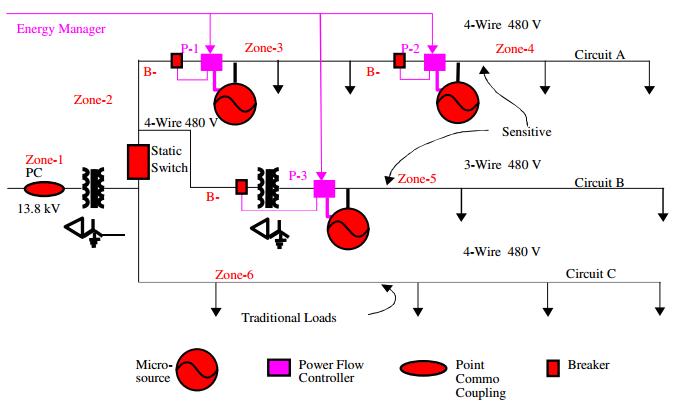
The CERTS Microgrid program has developed control methods to allow the installation of distributed generators (DGs) in commercial and industrial electric power systems in a “plug and play” manner. These control methods allow the generators to be electrically distributed, rather than be installed on the same electrical bus, and do not require intergenerator communications in order to maintain appropriate voltage and frequency at each generator. Note in figure that there is a communication link with the DGs that is labeled “Energy Manager”. This is a conventional energy manager that is used for power dispatch purposes, not for frequency or voltage control. This energy manager can use relatively slow communications links, such as telephone or internet, since it has no bearing on system stability.
Source:
John Stevens «CERTS Microgrid System Test». IEEExplore
Dr. Jorge Luis Mírez Tarrillo
Group of Mathematical Modeling and Numerical Simulation (GMMNS).
Universidad Nacional de Ingeniería. Lima, Perú.
E-mail: jmirez@uni.edu.pe
Website Personal: https://jorgemirez2002.wixsite.com/jorgemirez
Facebook http://www.facebook.com/jorgemirezperu
Linkedin https://www.linkedin.com/in/jorge-luis-mirez-tarrillo-94918423/
Scopus ID: https://www.scopus.com/authid/detail.uri?authorId=56488109800
Google Scholar: https://scholar.google.com/citations?user=_dSpp4YAAAAJ
MATLAB Group Admin in Facebook: https://www.facebook.com/groups/Matlab.Simulink.for.All
WhatsApp Channel/Canal: https://whatsapp.com/channel/0029VbCvpZsAYlUSz2esek2y

Sometimes, the reactive power in a electric system exceed the nominal capacity of condensers bank, therefore, all units capacitores is connected to give the maximum reactive power compensation possible. The figure is one of my simulations on Matlab and complement past post. Matlab is from MathWork Inc. The figure is the results of mathematical model of condensers bank operation (control and optimization).
Dr. Jorge Luis Mírez Tarrillo
Group of Mathematical Modeling and Numerical Simulation (GMMNS).
Universidad Nacional de Ingeniería. Lima, Perú.
E-mail: jmirez@uni.edu.pe
Website Personal: https://jorgemirez2002.wixsite.com/jorgemirez
Facebook http://www.facebook.com/jorgemirezperu
Linkedin https://www.linkedin.com/in/jorge-luis-mirez-tarrillo-94918423/
Scopus ID: https://www.scopus.com/authid/detail.uri?authorId=56488109800
Google Scholar: https://scholar.google.com/citations?user=_dSpp4YAAAAJ
MATLAB Group Admin in Facebook: https://www.facebook.com/groups/Matlab.Simulink.for.All
WhatsApp Channel/Canal: https://whatsapp.com/channel/0029VbCvpZsAYlUSz2esek2y

This is my simulation about the to work (on-off) of condenser bank. This bank is made by many condensers of different capacity. The model and simulation is implemented on Matlab of MathWork Inc. The little difference is result of maximun capacity and real reactive demand.
Dr. Jorge Luis Mírez Tarrillo
Group of Mathematical Modeling and Numerical Simulation (GMMNS).
Universidad Nacional de Ingeniería. Lima, Perú.
E-mail: jmirez@uni.edu.pe
Website Personal: https://jorgemirez2002.wixsite.com/jorgemirez
Facebook http://www.facebook.com/jorgemirezperu
Linkedin https://www.linkedin.com/in/jorge-luis-mirez-tarrillo-94918423/
Scopus ID: https://www.scopus.com/authid/detail.uri?authorId=56488109800
Google Scholar: https://scholar.google.com/citations?user=_dSpp4YAAAAJ
MATLAB Group Admin in Facebook: https://www.facebook.com/groups/Matlab.Simulink.for.All
WhatsApp Channel/Canal: https://whatsapp.com/channel/0029VbCvpZsAYlUSz2esek2y

One question that most system operators are concerned with is the optimised DG penetration level. Relationship regarding different cost models between optimum DG penetration level and interruption frequency is indicated in Figure.
Optimum micro-source penetration level is positive related with the interruption frequency without DG penetration; especially for average interruption costs, the relationship is almost linear. This relationship is important for systemplanning; as the system interruption frequency without DG penetration is generally known, the system operator is able to roughly determine of the optimum DG penetration level from reliability point of view
Dr. Jorge Luis Mírez Tarrillo
Group of Mathematical Modeling and Numerical Simulation (GMMNS).
Universidad Nacional de Ingeniería. Lima, Perú.
E-mail: jmirez@uni.edu.pe
Website Personal: https://jorgemirez2002.wixsite.com/jorgemirez
Facebook http://www.facebook.com/jorgemirezperu
Linkedin https://www.linkedin.com/in/jorge-luis-mirez-tarrillo-94918423/
Scopus ID: https://www.scopus.com/authid/detail.uri?authorId=56488109800
Google Scholar: https://scholar.google.com/citations?user=_dSpp4YAAAAJ
MATLAB Group Admin in Facebook: https://www.facebook.com/groups/Matlab.Simulink.for.All
WhatsApp Channel/Canal: https://whatsapp.com/channel/0029VbCvpZsAYlUSz2esek2y
FACTS devices can enhance the power flow on existing power lines. For the transmission line shown in figure, the sending end voltage isVS∠δS, the receiving end voltage is VR∠δR and the equivalent impedance of parallel connected lines isX. The power transfer through the lines is given by:

the figure also shows how FACTS devices act on the power transfer equation. The TCSC can change the impedance of the line, the STATCOM can control the voltage magnitude at

the terminal to which it is connected by injecting or absorbing reactive power and the UPFC can alter the phase angle of the sending end voltage, thus power flow through a line can be controlled in a number of ways.
Source:
SMART GRID
TECHNOLOGY AND APPLICATIONS
Janaka Ekanayake
Cardiff University, UK
Kithsiri Liyanage
University of Peradeniya, Sri Lanka
Jianzhong Wu
Cardiff University, UK
Akihiko Yokoyama
University of Tokyo, Japan
Nick Jenkins
Cardiff University, UK
A John Wiley & Sons, Ltd., Publication
Dr. Jorge Luis Mírez Tarrillo
Group of Mathematical Modeling and Numerical Simulation (GMMNS).
Universidad Nacional de Ingeniería. Lima, Perú.
E-mail: jmirez@uni.edu.pe
Website Personal: https://jorgemirez2002.wixsite.com/jorgemirez
Facebook http://www.facebook.com/jorgemirezperu
Linkedin https://www.linkedin.com/in/jorge-luis-mirez-tarrillo-94918423/
Scopus ID: https://www.scopus.com/authid/detail.uri?authorId=56488109800
Google Scholar: https://scholar.google.com/citations?user=_dSpp4YAAAAJ
MATLAB Group Admin in Facebook: https://www.facebook.com/groups/Matlab.Simulink.for.All
WhatsApp Channel/Canal: https://whatsapp.com/channel/0029VbCvpZsAYlUSz2esek2y

Electricity meters are used to measure the quantity of electricity supplied to customers as well as to calculate energy and transportation charges for electricity retailers and network operators. The most common type of meter is an accumulation meter, which records energy consumption over time. Accumulation meters in consumer premises are read manually to assess how much energy has been used within a billing period. In recent years, industrial and commercial consumers with large loads have increasingly been using more advanced meters, for example, interval meters which record energy use over short intervals, typically every half hour. This allows the energy suppliers to design tariffs and charging structures that reflect wholesale prices and helps the customers understand and manage their pattern of electricity demand. Smart meters are even more sophisticated as they have two-way communications and provide a real-time display of energy use and pricing information, dynamic tariffs and facilitate the automatic control of electrical appliances
Source:
SMART GRID
TECHNOLOGY AND APPLICATIONS
Janaka Ekanayake
Cardiff University, UK
Kithsiri Liyanage
University of Peradeniya, Sri Lanka
Jianzhong Wu
Cardiff University, UK
Akihiko Yokoyama
University of Tokyo, Japan
Nick Jenkins
Cardiff University, UK
A John Wiley & Sons, Ltd., Publication
Dr. Jorge Luis Mírez Tarrillo
Group of Mathematical Modeling and Numerical Simulation (GMMNS).
Universidad Nacional de Ingeniería. Lima, Perú.
E-mail: jmirez@uni.edu.pe
Website Personal: https://jorgemirez2002.wixsite.com/jorgemirez
Facebook http://www.facebook.com/jorgemirezperu
Linkedin https://www.linkedin.com/in/jorge-luis-mirez-tarrillo-94918423/
Scopus ID: https://www.scopus.com/authid/detail.uri?authorId=56488109800
Google Scholar: https://scholar.google.com/citations?user=_dSpp4YAAAAJ
MATLAB Group Admin in Facebook: https://www.facebook.com/groups/Matlab.Simulink.for.All
WhatsApp Channel/Canal: https://whatsapp.com/channel/0029VbCvpZsAYlUSz2esek2y

The communication infrastructure of a power system typically consists of SCADA systems with dedicated communication channels to and from the System Control Centre and a Wide Area Network (WAN). Some long-established power utilities may have private telephone networks and other legacy communication systems. The SCADA systems connect all the major power system operational facilities, that is, the central generating stations, the transmission grid substations and the primary distribution substations to the System Control Centre. The WAN is used for corporate business and market operations. These form the core communication networks of the traditional power system. However, in the Smart Grid,it is expected that these two elements of communication infrastructure will merge into a Utility WAN.
An essential development of the Smart Grid (see figure ) is to extend communication throughout the distribution system and to establish two-way communications with customers through Neighbourhood Area Networks (NANs) covering the areas served by distribution substations. Customers’ premises will have Home Area Networks (HANs). The interface of the Home and Neighbourhood Area Networks will be through a smart meter or smart interfacing device.
Source:
SMART GRID
TECHNOLOGY AND APPLICATIONS
Janaka Ekanayake
Cardiff University, UK
Kithsiri Liyanage
University of Peradeniya, Sri Lanka
Jianzhong Wu
Cardiff University, UK
Akihiko Yokoyama
University of Tokyo, Japan
Nick Jenkins
Cardiff University, UK
A John Wiley & Sons, Ltd., Publication
Dr. Jorge Luis Mírez Tarrillo
Group of Mathematical Modeling and Numerical Simulation (GMMNS).
Universidad Nacional de Ingeniería. Lima, Perú.
E-mail: jmirez@uni.edu.pe
Website Personal: https://jorgemirez2002.wixsite.com/jorgemirez
Facebook http://www.facebook.com/jorgemirezperu
Linkedin https://www.linkedin.com/in/jorge-luis-mirez-tarrillo-94918423/
Scopus ID: https://www.scopus.com/authid/detail.uri?authorId=56488109800
Google Scholar: https://scholar.google.com/citations?user=_dSpp4YAAAAJ
MATLAB Group Admin in Facebook: https://www.facebook.com/groups/Matlab.Simulink.for.All
WhatsApp Channel/Canal: https://whatsapp.com/channel/0029VbCvpZsAYlUSz2esek2y

The Figure is a schematic of a simple distribution network with distributed generation (DG).There are many characteristics of this network that differ from a typical passive distribution network. First, the power flow is not unidirectional. The direction of power flows and the voltage magnitudes on the network depend on both the demand and the injected generation. Second, the distributed generators give rise to a wide range of fault currents and hence complex protection and coordination settings are required to protect the network. Third, the reactive power flow on the network can be independent of the active power flows. Fourth, many types of DGs are interfaced through power electronics and may inject harmonics into the network. The Figure also shows a control scheme suitable for achieving the functions of active control. In this scheme a Distribution Management System Controller (DMSC) assesses the network conditions and takes action to control the network voltages and flows. The DMSC obtains measurements from the network and sends signals to the devices under its control. Control actions may be a transformer tap operation, altering the DG output and injection/absorption
of reactive power.
Source:
SMART GRID
TECHNOLOGY AND APPLICATIONS
Janaka Ekanayake
Cardiff University, UK
Kithsiri Liyanage
University of Peradeniya, Sri Lanka
Jianzhong Wu
Cardiff University, UK
Akihiko Yokoyama
University of Tokyo, Japan
Nick Jenkins
Cardiff University, UK
A John Wiley & Sons, Ltd., Publication
Dr. Jorge Luis Mírez Tarrillo
Group of Mathematical Modeling and Numerical Simulation (GMMNS).
Universidad Nacional de Ingeniería. Lima, Perú.
E-mail: jmirez@uni.edu.pe
Website Personal: https://jorgemirez2002.wixsite.com/jorgemirez
Facebook http://www.facebook.com/jorgemirezperu
Linkedin https://www.linkedin.com/in/jorge-luis-mirez-tarrillo-94918423/
Scopus ID: https://www.scopus.com/authid/detail.uri?authorId=56488109800
Google Scholar: https://scholar.google.com/citations?user=_dSpp4YAAAAJ
MATLAB Group Admin in Facebook: https://www.facebook.com/groups/Matlab.Simulink.for.All
WhatsApp Channel/Canal: https://whatsapp.com/channel/0029VbCvpZsAYlUSz2esek2y

Quienes hemos visto como funciona un banco de condensadores, podemos ver y escuchar el conectar y desconectar de los condensadores los cuales se van conectando dependiendo de la necesidad de potencia reactiva a inyectar y de las acciones del sistema de control. En la figura se muestra un ejemplo de funcionamiento de condensador para unos 100 estados o ciclos de trabajo, medida que he usado en esta figura, dado que la necesidad de potencia reactiva no depende de la escala de tiempo, es por lo general aleatoria, entonces lo que puedo ir determinando es si esta en conectado ON o desconectado OFF. Un sistema de ceros y unos sirven para identificar cada estado. La simulación está hecha en Matlab de MathWork Inc y complementa lo que post atrás es la ponencia que realice en Costa Rica durante el III Congreso Iberoamericano de Microredes con Generación Distribuida de Renovables. Favor difundir éste blog y si les interesa mis servicios, me escriben :)D
The information related to this post for sale for US $ 100.00. You can make payments through PayPal account: jorgemirez2002@gmail.com or send an e-mail to receive PayPal invoice and make your payment quickly and easily. Tell us (through e-mail) the name of the input or inputs that interests you. // La información relacionada con este post en venta por US $ 100.00. Usted puede hacer pagos a través de cuenta PayPal: jorgemirez2002@gmail.com o enviar un e-mail para recibir la factura de PayPal y hacer su pago de forma rápida y sencilla. Díganos (por medio de email) el nombre de la entrada o entradas que le interese.
Dr. Jorge Luis Mírez Tarrillo
Group of Mathematical Modeling and Numerical Simulation (GMMNS).
Universidad Nacional de Ingeniería. Lima, Perú.
E-mail: jmirez@uni.edu.pe
Website Personal: https://jorgemirez2002.wixsite.com/jorgemirez
Facebook http://www.facebook.com/jorgemirezperu
Linkedin https://www.linkedin.com/in/jorge-luis-mirez-tarrillo-94918423/
Scopus ID: https://www.scopus.com/authid/detail.uri?authorId=56488109800
Google Scholar: https://scholar.google.com/citations?user=_dSpp4YAAAAJ
MATLAB Group Admin in Facebook: https://www.facebook.com/groups/Matlab.Simulink.for.All
WhatsApp Channel/Canal: https://whatsapp.com/channel/0029VbCvpZsAYlUSz2esek2y

La energía reactiva solicitada por los diferentes dispositivos como motores eléctricos o equipos de electrónica de potencia es para poder funcionar, sin embargo, ocupan espacio dentro de la capacidad de transmisión de los conductores eléctricos, es por ello que hay que reducir dicho flujo a lo necesario que es la potencia activa, sin embargo, no puede ser sólo energía activa, dado que se entrar en una resonancia, pero si bien se puede trabajar en un factor de potencia lo más cercano a 1, pero no tanto que el sistema de control no lo pueda coordinar bien. La figura muestra una simulación del trabajo de un banco de condensadores, se puede apreciar tanto la potencia reactiva solicitada por la red eléctrica como la que brinda el banco de condensadores, ambos lo bastante cercanos que las curvas se parecen suporponer. Hecho en Matlab de MathWorks Inc para todos los interesados en los sistemas eléctricos y en el manejo adecuado del factor de potencia.
The information related to this post for sale for US $ 100.00. You can make payments through PayPal account: jorgemirez2002@gmail.com or send an e-mail to receive PayPal invoice and make your payment quickly and easily. Tell us (through e-mail) the name of the input or inputs that interests you. // La información relacionada con este post en venta por US $ 100.00. Usted puede hacer pagos a través de cuenta PayPal: jorgemirez2002@gmail.com o enviar un e-mail para recibir la factura de PayPal y hacer su pago de forma rápida y sencilla. Díganos (por medio de email) el nombre de la entrada o entradas que le interese.
Dr. Jorge Luis Mírez Tarrillo
Group of Mathematical Modeling and Numerical Simulation (GMMNS).
Universidad Nacional de Ingeniería. Lima, Perú.
E-mail: jmirez@uni.edu.pe
Website Personal: https://jorgemirez2002.wixsite.com/jorgemirez
Facebook http://www.facebook.com/jorgemirezperu
Linkedin https://www.linkedin.com/in/jorge-luis-mirez-tarrillo-94918423/
Scopus ID: https://www.scopus.com/authid/detail.uri?authorId=56488109800
Google Scholar: https://scholar.google.com/citations?user=_dSpp4YAAAAJ
MATLAB Group Admin in Facebook: https://www.facebook.com/groups/Matlab.Simulink.for.All
WhatsApp Channel/Canal: https://whatsapp.com/channel/0029VbCvpZsAYlUSz2esek2y
Blog in ENGLISH

Compra/Buy – Haz una donación/Make a donation

Dear reader, if you wish to make a donation or are interested in any information or code, please contact me (e-mail: jmirez@uni.edu.pe). Donations will allow you to continue studying and researching, and also to provide more information on this blog. My PayPal account is jorgemirez2002@gmail.com or if it is by bank transfer write to my email jmirez@uni.edu.pe. Any amount of money is welcome. Thank you.
Estimado lector, si desean hacer una donación o le interesa alguna información o código, favor ponerse en contacto con mi persona (e-mail: jmirez@uni.edu.pe). Las donaciones va a permitir seguir estudiando e investigando, y además, el poder brindar más información en este blog. Mi cuenta en PayPal es jorgemirez2002@gmail.com o si es por transferencia bancaria escribirme a mi correo jmirez@uni.edu.pe. Cualquier cantidad de dinero es bienvenido. Gracias.
Datos Generales
Good day. My full name is Jorge Luis MIREZ TARRILLO.
I am Peruvian and live in Lima, capital of Perú in South America.I am Mechanical Electrical Engineering, MSc Physics and Dr. Physics (title doctoral thesis: Control, Optimization, and Management of Microgrid Current Direct)
Too, actually job as Principal Professor in Faculty of Oil, Gas and Petrochemical Engineering of Universidad Nacional de Ingeniería (National University of Engineering) in Lima – PERU (Courses: Modern Physics, Differential Equations and Research's Methodology)
My subjects of my interest are control, signal processing, optimization, simulation, biomedical research, smart grid, microgrid, water.
I have experience in Matlab/Simulink programming, biomedical equipment, electrical systems, renewable energies, microgrids, saturated steam systems 100 psi and organizing academic events.

Comentarios Recientes
Elementos que compon… en J506: Los elementos de un paqu… Dr. Jorge Mírez en Message by IEEE Community Dr. Jorge Mírez en J546: Simulación de campos mag… jose luis huayanay v… en Message by IEEE Community Cesar Aviles en J546: Simulación de campos mag… Dr. Jorge Mírez en J518: La herramienta pdetool d… Dr. Jorge Mírez en J496: Simulación en Matlab/Sim… Raúl Barrios Elizarr… en J496: Simulación en Matlab/Sim… jose luis huayanay v… en J518: La herramienta pdetool d… MSc. Jorge Mírez en J281: La Rosa de Vientos: Frec…


Debe estar conectado para enviar un comentario.